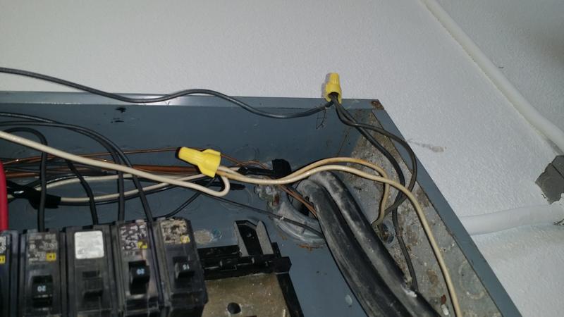
How would you address this? Three wires under a nut.
Michael, This is a good course to take. it will help a lot.
As for this picture, from what we can see, it’s ok
http://www.nachi.org/electricalcoursereleased2006.htm
No issue.
The manufacturers do have specification of how many and what size wires can be combined in the wire nuts.
Thanks for the responses. My class found this yesterday and this was outlined as a fault equivalent to a double tapped breaker. I can see that the manufacturers design the nuts to accommodate three #12 wires.
So, this being present IN the service panel doesn’t make this an issue?
Correct. Nor is it an issue along the circuit as long as it’s within a listed junction box.
Wow!
What you see is the accepted fix for a double tapped breaker.
You need to be asking your teacher some pointed questions.
Have him explain why he thinks it is wrong.
His reasoning is because it is a split in the circuit, effectively creating two individual branches.
Which is perfectly acceptable, although not a preferred practice.
Thanks John, I have passed that but I will be rereading it several times.
What class are you taking and what did your instructor have to say about it?
Wow, I am sorry to see that your instructor is so poorly prepared to teach your class. As the others have said there is no issue as long as the combination of wires falls into the correct range for the connector.
While only for Ideal brand connectors you can see a range chart from this link that can be downloaded.
http://www.idealindustries.com/products/wire_termination/twist-on/
Do not just assume that 3 #12 are acceptable as they may be out of the range. The package will have the combinations listed. A trip to a supply house might be in order to gain hands on with the products.
Thanks for the clarifications. Glad I asked.
I wonder what he thinks happens in a junction box or if pigtails are used. Circuits are not always run in a linear fashion.
Michael, If I were you I would be Real concerned as to how many other things your instructor has been misleading you with.
Yes, that’s why I have been asking a lot of questions on the forum - to get a secondary source of information on things that sound questionable. I have to say that the live course is a great way to be exposed to aspects that online learning can’t cover well. My teachers have been great. I’m glad I did most of the InterNACHI course before I did this course.
The wire nut is not the issue but if those are two different circuit neutrals pigtailed to the neutral bar then you have created a MWBC and the circuits would need to be on opposite phases or the amperage in the pigtail would be additive from both circuits.
The circuit runs one hot / one neutral to a gfci directly below the service panel. They come back out and split under the nuts, branching off to 1) a non gfci outlet & 2) ceiling lights.
Is there any chance that your instructor is from Canada?
@DHAYS -
This is actually incorrect (sorry) as the manufacturers will provide a range of conductors that each wire binding device (pressure connector) can support. They also may even tell you not to pre-twist conductors as well before entering the pressure connector.
However, this is a good place to send a reminder…many times you may see this setup in a panel and knowing (as many have said, it acceptable) yet you run into a case where you see a 10 AWG and a 12 AWG under the same pressure connector…at that point always make sure the smaller conductor is protected at it’s ampacity…for example (not talking about motors and the like…just typical branch circuits in a dwelling) if the above happened and they placed the 10 AWG on a 30A OCPD [Overcurrent Protective Device] it would not be protecting the 12 AWG which needs to be protected with a 20 A OCPD.
Just things to think about…obviously the OP’s example is not like this…but figured it was a good moment for a little edumacation.