Inspecting Off-Grid Photovoltaic Systems

An off-grid home (front)
Most of these photos show an off-grid home built in 1984 that originally had a PV system installed. The system was upgraded in 2006 using both old and new components. Some aspects of the upgrade failed to meet current safety standards; for that reason, it is a good representation of some of the conditions that inspectors may encounter.
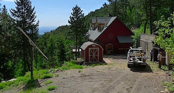
Off-grid home (rear) with a pole-mounted array at left
An off-grid system describes a home’s electrical system that is not connected to the local power utility’s electrical grid. Instead, the home uses rectangular solar cells that are connected together to form PV modules, commonly called panels, that convert sunlight into electricity. This electricity charges a bank of batteries that power the home, as well as store power for use during the night and when the sun is not shining strongly enough to allow the panels to produce enough electricity to meet the home’s electrical demands. Most homes have a backup generator that will automatically activate to charge the batteries when a sensor indicates that the charge has dropped to a specified level. When the batteries are full, excess electricity produced by the panels may be diverted from the batteries to the home.

Component locations
Off-Grid vs. Grid-Tie
Some systems use batteries and are also connected to the public utility power grid (called grid-tie systems). Such systems have different inspection requirements from those that are entirely off-grid. The most important difference is that grid-tie systems can energize utility power lines, potentially endangering power company employees working on them. Grid-tie systems require specific disconnects and labeling that are different from those for off-grid systems. Here’s how to tell the difference between grid-tie and off-grid systems.

Grid-tie system for a home with an interior main panel

Grid-tie labeling details
The labels in the photos above are for a grid-tie system whose main electrical panel is located inside the home. Labeling must be visible from the home’s exterior so that power company employees and firefighters can see it without having to enter the home.
The labels depicted below indicate that the PV installers used an existing exterior main panel. In both systems, the original electrical meter has been replaced with a net meter that spins backwards when the PV system produces more electricity than the home uses.

Grid-tie system using an existing exterior main panel

Grid-tie labeling details
History of Off-Grid Systems
Off-grid systems first came into residential use primarily in the late 1970s. Older systems and components may not be well-designed, and some older systems still around today may have been added onto – possibly multiple times, and not always by people who were properly trained to do so. The popularity of green energy in recent decades means that system designs and components have improved, along with the training of qualified contractors.
Basic Operation

Overview diagram of an off-grid system
(Courtesy of Backwoods Solar)
Sunlight striking solar cells is converted to direct current (DC) electricity, which travels through weather- and UV-resistant conductors to a combiner box.

Six PV modules with electrical connections.
The combiner box is located about 18 inches down from the top of the pole.

A combiner box. The round canister is a surge protector for protection
from lightning strikes. It contains an energy-absorbing foam.

A defect discovered at this combiner box includes
the damaged insulation that exposes the conductors to weather.
At the combiner box, electrical current from the different modules is combined and transferred to a single conductor, which routes electrical current to a charge controller. The single conductor should be encased in a conduit.
In the photo below, the conductor is not encased in a conduit. This condition exposes the conductor to damage from impact or abrasion.

The conductor should be encased in a conduit.
The conductor is routed through a hole in the roof, and the penetration is protected with sealant instead of flashing. Sealant eventually dries, shrinks and cracks, leaving an avenue for moisture intrusion. A conductor that is properly installed is encased in a metal conduit. If the conduit does not enter the home structure, a plastic conduit is acceptable, but not preferable.

This conductor is improperly routed through the roof.
The charge controller monitors the condition of the battery bank and acts as a transformer, allowing the batteries to be charged as needed, and limiting the amount of current used in charging so that the batteries don’t overheat. Overheated batteries could lead to an explosion that could spray acid over everything nearby.
In addition to routing electrical current to the batteries, the charge controller may also divert current to a DC load center that controls branch circuits and feeds lighting and/or appliances that run on DC instead of AC (active current).
From the batteries, and sometimes directly from the charge controller, the current flows through an inverter that changes the electricity from DC to AC so that it can be utilized by conventional appliances and devices in the home. Current moves from the inverter to an AC load center (the main electrical panel); from there, it is routed to branch circuits that feed devices, lighting and appliances that use conventional 120- or 240-volt AC current.
The backup generator has a starter battery that should have its own charging system separate from the home’s system. If the battery is dependent on the home system for starting the generator, when the PV batteries are too low to provide the home with power, they may be too low to actually start the generator. The generator should be connected to an automatic transfer switch that will allow the generator to charge the batteries but which may also allow the generator to provide power directly to the AC load center (the home’s main electrical panel).
Design Considerations
An alternative is to lower the home’s electrical demand. One way to achieve this is by incorporating passive solar design features, such as proper window type and orientation, with adequate thermal mass to collect, store and release heat. Other ways to reduce demand include the use of smaller, more energy-efficient electrical appliances, as well as gas-powered appliances, such as refrigerators, dryers and ranges. Residents whose homes rely on PV systems should avoid using high-demand electrical appliances, such as electric heaters.

The backside of a gas-fired refrigerator
In a home with a small PV system installed where there are also high-demand electrical appliances, the inspector should recommend that the PV system’s size be evaluated by a qualified specialist. The system in these photos is sufficient for a long weekend, at best. It would be inadequate for a home that is occupied full-time.
Case Study Controls
The photo below shows the controls for the home’s upgraded system, which are located in an outbuilding, along with the batteries that probably serve the new system only. The batteries are installed in a crawlspace beneath the outbuilding’s floor. No other batteries were located on the property at the time of the inspection.

The controls

Number 1 is the service disconnect.
Two breakers form the service disconnect. The control on the left controls the AC power going from the inverters to the main electrical panel in the house. The one on the right controls the power from the generator to the home.

Number 2 is the generator start module.
The generator start module senses the battery’s condition and activates the generator when the PV system can’t provide enough power.

Number 3 is one of two inverters located next to each other.
Newer inverters usually have a digital readout showing the amperage produced by the system, and sometimes other information. Although these inverters had labels for a digital readout installed, the actual readout was never installed. Each inverter produces 120 volts only. Because the home is located in the mountains, it had a well deep enough to require a 240-volt pump, so two inverters were needed.

Number 4 is the charge controller.
There are three defects related to the charge controller:
- The conductors should be encased in a conduit.
- The charge controller should not be connected to the inverter terminals.
- There should be a disconnect between the charge controller and the batteries. The disconnect should be located in the connectors to the right, since those lead to the battery bank.
PV panels are flat-plate collectors in which rectangular, silicon-based solar cells are grouped, electrically connected, and sandwiched between a PVC back and a tempered glass face to form modules. Modules may be combined to produce 12, 24 or 48 volts. Modules may be rated by volts, watts or amps, although the amp rating is the best indicator of the charging power of the module.

Two modules with 96 solar cells each
The photos above and below show solar cells installed in modules.

A close-up of two solar cells
Solar cells may be manufactured using a monocrystalline method that leaves the face of the module looking fairly uniform. The photo blow shows modules manufactured using the monocrystalline method.

Monocrystalline solar cells

Polycrystalline solar cells
Solar cells may also be manufactured using a polycrystalline method utilizing flakes of silicon that are visible. This is not a defect, and modules may come off the production line looking like this.
A typical module may carry a 25-year warranty on performance, guaranteeing 80% of design output, and a five-year manufacturer’s warranty on materials and workmanship.
Modules are installed in groups on a solar mount (metal rack). A group of modules is called an array. Arrays can be mounted on a rooftop, a pole, or on racks that can be adjusted to change the tilt angle. The photos below show a variety of mounting methods.

An array mounted flush with the roof

Roof-mounted array

Pole-mounted array

Rack-mounted array
Directional Orientation
In order to collect sunlight most efficiently, the array should face as close to true south as possible. True south is not the same as magnetic south, and the correction will vary from place to place. Accordingly, arrays are usually installed on roof slopes most closely facing south. The farther from true south the array faces, the less efficient it will be. Some array mounts are designed to track the sun across the sky. These systems are very efficient but more expensive. An inspection should mark the position of the array and mount at the beginning of the inspection and again upon completion to confirm that it’s operating.
Tilt
As the seasons change and the sun crosses higher in the sky during summer and lower in the sky during winter, the optimum tilt angle will change. The amount of change will also vary with latitude. In general, the optimum winter angle is around 20 degrees steeper than the latitude.
If the home were located in Key West, Florida, which is at about 25 degrees latitude, the best summer angle of tilt for the array would be almost flat, and the best winter angle would be about 46 degrees.
If the home were in Albuquerque, New Mexico, which is at 35 degrees latitude, the best summer angle would be about 8 degrees and the best winter angle would be about 55 degrees.
If the home were in Winnipeg, Manitoba, Canada, which is at 50 degrees latitude, the best summer angle would be about 22 degrees and the best winter angle would be about 68 degrees.
Some mounts are adjustable so that the angle of tilt can be changed with the season. With stationary mounts, the system designer must pick a happy medium.

Changed roof angle
In the photo above, the roof angle has been changed to optimize the tilt of the panels, which are solar thermal (hot water) panels.

Evacuated tube solar thermal/PV comparison
Looking at this same roof from the front, it’s easier to see the difference between the solar thermal panels above and the PV panels below.

Flat-plate solar thermal and PV comparison
Inspectors may occasionally encounter flat-plate solar thermal panels like those mounted at the back of this home. Although they may look similar to PV arrays, solar thermal panels have plumbing connections, not electrical connections.
Shading
Anything that shades the array, such as trees, other parts of the roof, chimneys, and geographical features such as mountain ridges, will reduce the amount of power the array produces. Full, direct sunshine is necessary for full power.
Inspecting the Array
Roof-mounted arrays rest on hardware called standoffs. Standoffs penetrate the roof-covering material and should be properly flashed and not just protected by a sealant.

Improperly installed standoffs
The photo above shows standoffs protected by sealant alone. As already mentioned, sealant eventually dries, shrinks and cracks, leaving an avenue for moisture intrusion. The photo below shows a standoff properly flashed.

Properly installed standoffs
Standoffs should also be properly fastened. The photo below shows a standoff installed over felt underlayment, bedded in roof cement, and fastened with structural screws.

There should be evidence of some sort of grounding system, such as a copper wire attached to the metal mounting system and going to a driven rod.

Copper ground wire
Electrical conductors, including grounded conductors, have sizing requirements that an inspector will not be qualified to confirm as proper.
3. Conductors:
Conductors should not be in contact with the roof. This can result in abrasion and damage. If the conductors are abraded down to the bare wire and they come into contact with the metal mount and you come into contact with the mount, you can be shocked or electrocuted.

Conductors in contact with shingles
Batteries
Lead-Acid
In PV systems, DC power is usually stored in 12-volt, deep-cycle, lead-acid batteries. Deep-cycle batteries are built to discharge to a lower point than conventional 12-volt batteries, such as car batteries. Car batteries are shallow-cycle, manufactured for less than 20% discharge with immediate re-charge, and should not be used. Even deep-cycle batteries should not discharge more than 50%, and should be charged immediately to 100% when they get low. Excessive discharge will damage the batteries, as will continued over-charging. Operating the batteries with low water levels will also damage them. Only distilled water should be used. Batteries should be clean. The condition of the batteries can be checked using a hydrometer to check the fluid in a representative number of cells. All cells in all batteries should be checked several times a year as part of regular home maintenance.
The plates in lead-acid batteries will accumulate sulfates over time. Sulfates are removed by a process called equalizing, which is a process of over-charging the batteries to a point at which the fluid starts to boil. It should be done on a regular basis and may be done manually, or the charge controller may be programmed to do it.
Batteries need regular maintenance, which is something that not all clients will be vigilant about. Determining what those maintenance requirements are exceeds the scope of a home inspection. Batteries are expensive to replace, so inspectors should do their best to protect their clients from unpleasant surprises and avoid speculating on the remaining service life of the batteries. Warranties are sales tools and don’t necessarily reflect the expected service life. Service life is affected by the brand, model and quality of the batteries, as well as their installation and maintenance. Batteries are a part of the PV system that is best evaluated by a specialist.
RV and Marine
This is a common 12-volt battery. Their design discharge maximum is about half way between a deep cycle and a shallow cycle, and they have medium expected service lives.
Sealed Batteries
Sealed batteries are easy to recognize because there are no caps on the tops of the batteries for adding water to the cells. Gel or AGM (absorbed glass mat) sealed batteries can work well for PV systems. They’re clean and safe, but they can be easily damaged by over-charging and require precise charging controls.
Nickel Cadmium (Alkaline) Batteries
Deep discharge and failure to recharge do not shorten alkaline battery life. Finding good used ones is difficult, and proper disposal and recycling can be difficult and costly.
Battery Chargers
Battery chargers convert AC power from the generator into low-voltage DC to charge the batteries. Most chargers costing less than $2,500 have low peak voltage that often causes them to give only a small percentage of their claimed charge rate. Some systems may have a voltage booster added to improve the charge rate. Generators need to be properly sized. There can also be compatibility problems between generators and chargers. This is another area best left to a specialist.
Case Study: Older System
Array/Inverter
An inspector from a firm that specializes in PV installation spent about three hours on the property. The older panels on the roof did not appear to be connected to an inverter, so, without a readout, it was not confirmed that they were producing electricity (since the roof was steeper than the PV inspector wanted to walk). There was no obvious termination of the conductor off the array, unless it terminated at the inoperable inverter hanging on the wall in the main floor’s mechanical room. The conductor for the inverter entered the ceiling directly below the point at which the conductor from the array entered the roof. There was no labeled disconnect for this older system. There was no battery bank or charge controller.

Inoperable inverter
Heating System
In the crawlspace was an inoperable boiler that had, at some point, supplied hot water for the baseboard hot-water heating system.


On the wall next to the boiler was an electrical panel labeled “12-volt DC zone relays 24-volts AC,” along with an inexpensive RadioShack® inverter. The PV inspector’s report made no mention of this system.
Case Study: Newer System
The two photos below show the battery bank. There are a number of defects visible.

Battery bank

Battery bank
Abandoned wiring should be dealt with. It should be confirmed that wiring is properly terminated, or the wiring should be removed.
Conductors feeding batteries should be sealed where they pass through the floor.

Holes need sealing
All splices should be contained in proper junction boxes with listed covers.

Exposed splices

Ventilation pipe
When batteries are being equalized, they off-gas a mixture of oxygen and hydrogen, which is flammable. A means of ventilating the area containing the batteries should be installed and should terminate at the exterior. In the first two photos above, the PVC pipe was installed to provide this ventilation, but as is evident in second photo, it doesn’t terminate at the exterior, but at a floor vent in the room above it that holds electrical equipment, most of which appeared to be abandoned. The amount of ventilation required depends on the size of the battery bank and the area in which it’s installed.

Ventilation pipe termination at floor drain
At this property, there were two abandoned batteries on-site: one in the bank of batteries in the outbuilding’s crawlspace, and one in a room on the main floor of the outbuilding. Abandoned batteries can leak acid, which is toxic and a hazard, especially around pets and children. If someone drops a metal tool across the posts, there is a danger of explosion or fire.

Abandoned batteries
Digital Readout
A digital readout was located in the home above laundry appliances, which is an undesirable location due to the high humidity and its potentially damaging effect on digital electronic equipment.

Digital readout
The digital readout showed “float, bulk, eq,” each of which describers a level of charging the batteries. Batteries may be charged at one of four different levels, depending on the conditions:
- float is a trickle charge;
- absorb is a medium charge;
- bulk is a strong charge; and
- equalize is an over-charge used for maintenance purposes.
Inspectors without specialized training should not touch the readout controls. Touching them risks changing crucial settings.
Raceway
A drainage duct buried in soil extended from the outbuilding containing PV equipment to the home’s crawlspace. PV electrical conductors were routed through this duct.

Culvert used as electrical raceway
There was nothing installed to prevent rodent entry, and there was evidence of rodent nesting activity in the duct (fir twigs and insulation scraps). The presence of rodents means that there exists the possibility that the conductors may be damaged by chewing.
Case Study: Conclusion
A thorough inspection, including tracing the wiring (and possibly invasive measures), would be required to determine the actual condition of this older system. This work lies beyond the budget of a typical PV inspection, and the buyer passed on the property, so no further evaluation took place. A system in this condition is not unusual. Home inspectors can expect to run across old systems of a number of different configurations from the late 1970s and early 1980s, when government and utility incentives made it financially attractive to have these systems installed. In rural areas over the years, even without incentives, homeowners have continued to install off-grid systems because it is less expensive than bringing in utilities and because they like the idea of being independent of the local utility power grid.
Although the state of knowledge concerning PV systems has improved recently, many systems have been installed by those only marginally qualified to do so. A thorough inspection of these systems takes expertise developed by special training and experience. It’s good for home inspectors to be knowledgeable enough to explain why a specialist inspection is needed, but inspectors should understand their limitations in trying to perform full inspections of off-grid systems. Home inspectors without the proper expertise should recommend that these systems be inspected by a contractor familiar with their installation and repair. In some parts of North America, finding a qualified contractor may be difficult. A local electrician who is not qualified should not be a substitute for a qualified specialist just for the sake of convenience.
If finding someone qualified to inspect the system is difficult, it may be even more difficult to find someone willing to perform routine maintenance on the system.
