Structural Connection Design for the Home Inspector
General

The objectives of connection design are:
- to transfer loads resisted by structural members and systems to other parts of the structure to form a continuous load path;
- to secure nonstructural components and equipment to the building; and
- to fasten members in place during construction to resist temporary loads during installation (i.e., finishes, sheathing, etc.).
The photo above shows an anchor bolt connecting a wooden sill plate to the top of a concrete foundation.
This article focuses on conventional wood connections that typically use nails, bolts, and some specialty hardware. The procedures for designing connections are based on the National Design Specification for Wood Construction (NDS). Also addressed are the relevant concrete and masonry connections prescribed in accordance with the applicable provisions of Building Code Requirements for Structural Concrete (ACI-318) and Building Code Requirements for Masonry Structures.
For most connections in typical residential construction, the connection design may be based on prescriptive tables found in the applicable residential building code. Table 1 below depicts a commonly recommended nailing schedule for wood-frame homes.
TABLE 1. Recommended Nailing Schedule for a Wood-Frame Home

The information included in this table is based on current industry practices and other sources.
The designer should verify that the connection complies with local requirements, practice, and design conditions for residential construction. A connection design based on the NDS or other sources may be necessary for special conditions, such as high-hazard seismic or wind areas, and when unique structural details and/or materials are used.
In addition to the conventional fasteners mentioned above, many specialty connectors and fasteners are available on today’s market. The reader is encouraged to gather, study and scrutinize manufacturer literature regarding specialty fasteners, connectors and tools that meet a wide range of connection needs.
Types of Mechanical Fasteners
Mechanical fasteners that are generally used for wood-framed house design and construction include the following:
Nails
Several characteristics distinguish one nail from another. Figure 1 depicts key features for a few types of nails that are essential for wood-frame design and construction. This section discusses some of a nail’s characteristics relative to structural design. For additional information, the reader is referred to Standard Terminology of Nails for Use with Wood and Wood-Based Materials (ASTM F547) and Standard Specifications for Driven Fasteners: Nails, Spikes and Staples (ASTM F 1667).
- nails and spikes;
- bolts;
- lag bolts (lag screws); and
- specialty connection hardware.
Nails
Several characteristics distinguish one nail from another. Figure 1 depicts key features for a few types of nails that are essential for wood-frame design and construction. This section discusses some of a nail’s characteristics relative to structural design. For additional information, the reader is referred to Standard Terminology of Nails for Use with Wood and Wood-Based Materials (ASTM F547) and Standard Specifications for Driven Fasteners: Nails, Spikes and Staples (ASTM F 1667).
FIGURE 1. Elements of a Nail and Nail Types

The most common nail types used in residential wood construction follow:
- Common nails are bright, plain-shank nails with a flat head and diamond point. The diameter of a common nail is larger than that of sinkers and box nails of the same length. Common nails are used primarily for rough framing.
- Sinker nails are bright or coated slender nails with a sinker head and diamond point. The diameter of the head is smaller than that of a common nail with the same designation. Sinker nails are used primarily for rough framing and applications where lumber splitting may be a concern.
- Box nails are bright, coated or galvanized nails with a flat head and diamond point. They are made of lighter-gauge wire than common nails and sinkers, and are typically used for toe-nailing and many other light framing connections where splitting of lumber is a concern.
- Cooler nails are generally similar to the nails described above, but with slightly thinner shanks. They are commonly supplied with ring shanks (i.e., annular threads) as a drywall nail.
- Power-driven nails (and staples) are produced by a variety of manufacturers for several types of power-driven fasteners. Pneumatic-driven nails and staples are the most popular power-driven fasteners in residential construction. Nails are available in a variety of diameters, lengths, and head styles. The shanks are generally cement-coated and are available with deformed shanks for added capacity. Staples are also available in a variety of wire diameters, crown widths, and leg lengths.
TABLE 2. Nail Types, Sizes and Dimensions

There are many types of nail heads, although three types are most commonly used in residential wood framing:
- The flat nail head is the most common head. It is flat and circular, and its top and bearing surfaces are parallel but with slightly rounded edges.
- The sinker nail head is slightly smaller in diameter than the flat nail head. It also has a flat top surface; however, the bearing surface of the nail head is angled, allowing the head to be slightly countersunk.
- Pneumatic nail heads are available in the types described above; however, other head types, such as a half-round or D-shaped heads, are also common.
The nail tip, as illustrated in Figure 1, is the end of the shank–usually tapered–that is formed during manufacturing to expedite nail driving into a given material. Among the many types of nail points, the diamond point is most commonly used in residential wood construction. The diamond point is a symmetrical point with four approximately equal beveled sides that form a pyramid shape. A cut point used for concrete cut nails describes a blunt point. The point type can affect nail drivability, lumber splitting, and strength characteristics.
The material used to manufacture nails may be steel, stainless steel, heat-treated steel, aluminum, or copper, although the most commonly used materials are steel, stainless steel, and heat-treated steel. Steel nails are typically formed from basic steel wire. Stainless steel nails are often recommended in exposed construction near the coast or for certain applications, such as cedar siding, to prevent staining. Stainless steel nails are also recommended for permanent wood foundations (PWFs). Heat-treated steel includes annealed, case-hardened, or hardened nails that can be driven into particularly hard materials, such as extremely dense wood or concrete.
Various nail coatings provide corrosion resistance, increased pullout resistance, or ease of driving. Some of the more common coatings in residential wood construction are described below:
- Bright. Uncoated and clean nail surface.
- Cement-coated. Coated with a heat-sensitive cement that prevents corrosion during storage and improves withdrawal strength, depending on the moisture and density of the lumber, along with other factors.
- Galvanized. Coated with zinc by barrel-tumbling, dipping, electroplating, flaking, or hot-dipping to provide a corrosion-resistant coating during storage and after installation for either performance or appearance. The coating thickness increases the diameter of the nail and improves withdrawal and shear strength.
Bolts
Bolts are often used for heavy connections and to secure wood to other materials, such as steel or concrete. In many construction applications, however, special power-driven fasteners are used in place of bolts. Refer to Figure 2 for an illustration of some typical bolt types and connections for residential use.
FIGURE 2. Bolt and Connection Types

In residential wood construction, bolted connections are typically limited to wood-to-concrete connections unless the home is constructed in a high-hazard wind or seismic area, and hold-down brackets are required to transfer shear wall overturning forces. Foundation bolts, typically embedded in concrete or grouted masonry, are commonly referred to as anchor bolts, J-bolts, or mud-sill anchors. Another type of bolt sometimes used in residential construction is the structural bolt, which connects wood to steel or wood to wood. Low-strength ASTM A307 bolts are commonly used in residential construction as opposed to high-strength ASTM A325 bolts, which are more common in commercial applications. Bolt diameters in residential construction generally range from 1/4- to 3/4-inch, although 1/2- to 5/8-inch-diameter bolts are most common, particularly for connecting a 2x wood sill to grouted masonry or concrete.
Bolts, unlike nails, are installed in pre-drilled holes. If the holes are too small, the possibility of splitting the wood member increases during installation of the bolt. If bored too large, the bolt holes encourage non-uniform dowel (bolt) bearing stresses and slippage of the joint when loaded. NDS specifies that bolt holes should range from 1/32- to 1/16-inch larger than the bolt diameter to prevent splitting and to ensure reasonably uniform dowel-bearing stresses.
Specialty Connection Hardware
Many manufacturers fabricate specialty connection hardware. The load capacity of a specialty connector is usually obtained through testing to determine the required structural design values. The manufacturer’s product catalogue typically provides the required values. Thus, the designer can select a standard connector based on the design load determined for a particular joint or connection. However, the designer should carefully consider the type of fastener to be used with the connector; sometimes a manufacturer requires or offers proprietary nails, screws, or other devices. It is also recommended that the designer verify the safety factor and strength adjustments used by the manufacturer, including the basis of the design value. In some cases, as with nailed and bolted connections in the NDS, the basis is a serviceability limit state (i.e., slip or deformation), and not ultimate capacity.
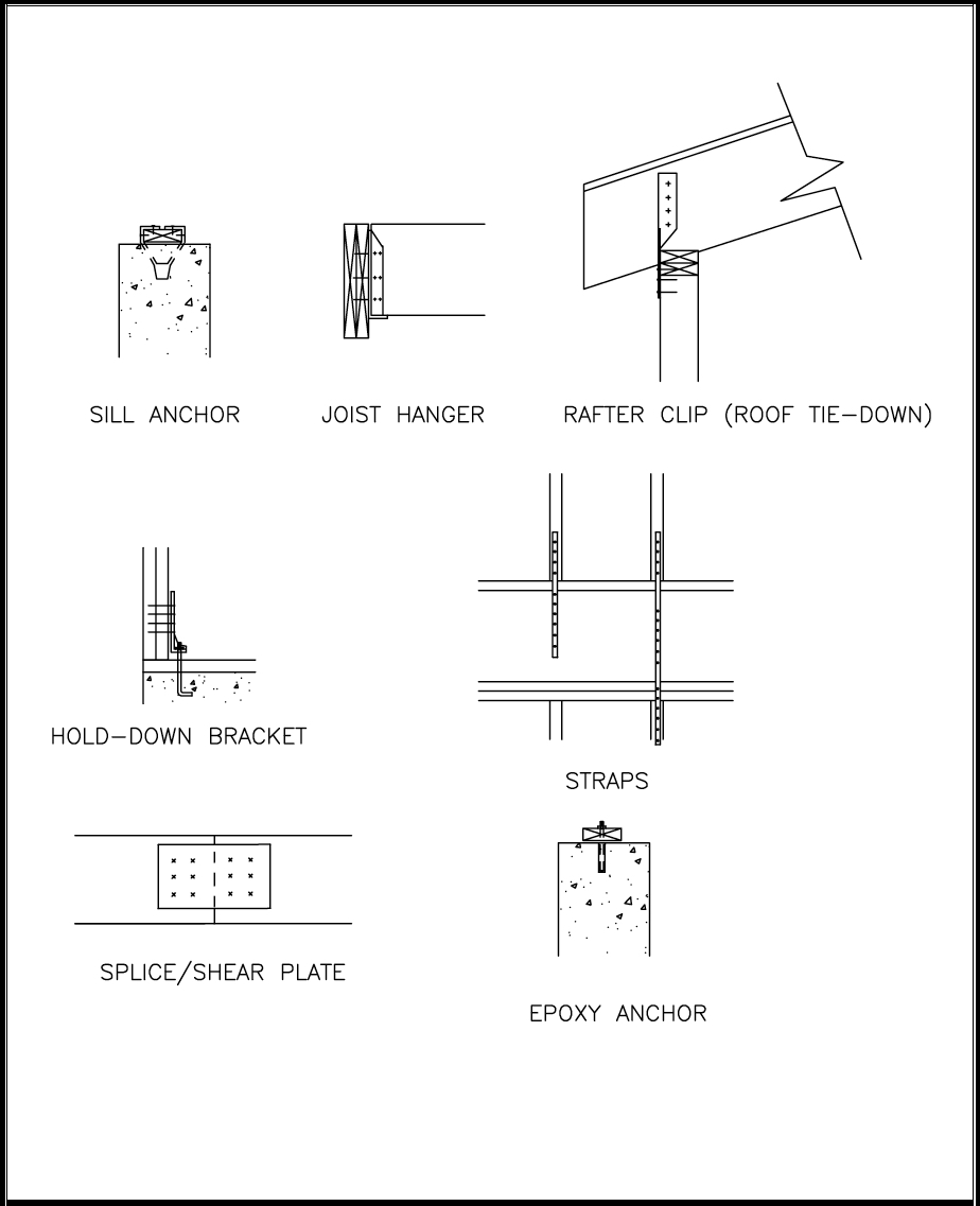
A few examples of specialty connection hardware are illustrated in Figure 3 and discussed below:
- Sill anchors are used in lieu of foundation anchor bolts. Many configurations are available in addition to the one shown in Figure 3.
- Joist hangers are used to attach single or multiple joists to the side of girders or header joists.
- Rafter clips and roof tie-downs are straps or brackets that connect roof framing members to wall framing to resist roof uplift loads associated with high-wind conditions.
- Hold-down brackets are brackets that are bolted, nailed, or screwed to wall studs or posts and anchored to the construction below (concrete, masonry or wood) to hold down the end of a member or assembly (i.e., shear wall).
- Strap ties are pre-punched straps or coils of strapping that are used for a variety of connections to transfer tension loads.
- Splice plates or shear plates are flat plates with pre-punched holes for fasteners to transfer shear or tension forces across a joint.
- Epoxy-set anchors are anchor bolts that are drilled and installed with epoxy adhesives into concrete after the concrete has cured, and sometimes after the framing is complete so that the required anchor location is obvious.
FIGURE 3. Specialty Connector Hardware
Lag Screws
Lag screws are available in the same diameter range as bolts; the principal difference between the two types of connectors is that a lag screw has screw threads that taper to a point. The threaded portion of the lag screw anchors itself in the main member that receives the tip. Lag screws (often called lag bolts) function as bolts in joints where the main member is too thick to be economically penetrated by regular bolts. They are also used when one face of the member is not accessible for a through-bolt. Holes for lag screws must be carefully drilled to one diameter and depth for the shank of the lag screw and to a smaller diameter for the threaded portion. Lag screws in residential applications are generally small in diameter and may be used to attach garage door tracks to wood framing, steel angles to wood framing supporting brick veneer over wall openings, various brackets or steel members to wood, and wood ledgers to wall framing.
Wood Connection Design
General
This section covers the design procedures for nails, bolts, and lag screws. The procedures are intended for allowable stress design (ASD) such that loads should be determined accordingly. Other types of fastenings are addressed by the National Design Specification for Wood Construction (NDS) but are rarely used in residential wood construction. The applicable sections of the NDS related to connection design as covered in this article include:
- NDS 7 – Mechanical Connections (General Requirements);
- NDS 8 – Bolts;
- NDS 9 – Lag Screws; and
- NDS 12 – Nails and Spikes.
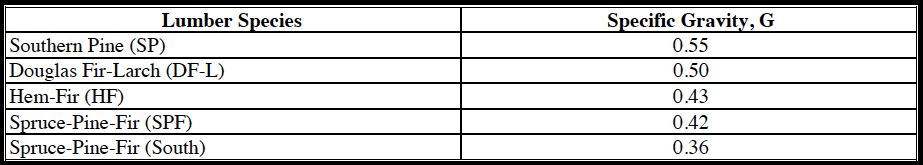
While wood connections are generally responsible for the complex, nonlinear behavior of wood structural systems, the design procedures outlined in the NDS are straightforward. The NDS connection values are generally conservative from a structural safety standpoint. Further, the NDS’s basic or tabulated design values are associated with tests of single fasteners in standardized conditions. As a result, the NDS provides several adjustments to account for various factors that alter the performance of a connection; in particular, the performance of wood connections is highly dependent on the species (i.e., density or specific gravity) of wood. Table 3 provides the specific gravity values of various wood species typically used in house construction.
TABLE 3. Common Framing Lumber Species and Specific Gravity Values
The moisture condition of the wood is also critical to long-term connection performance, particularly for nails in withdrawal. In some cases, the withdrawal value of fasteners installed in damp lumber can decrease by as much as 50% over time as the lumber dries to its equilibrium moisture content (EMC). At the same time, a nail may develop a layer of rust that increases withdrawal capacity. In contrast, deformed shank nails tend to hold their withdrawal capacity much more reliably under varying moisture and use conditions. For this and other reasons, the design nail withdrawal capacities in the NDS for smooth-shank nails are based on a fairly conservative reduction factor, resulting in about one-fifth of the average ultimate tested withdrawal capacity. The reduction includes a safety factor as well as a load-duration adjustment (i.e., decreased by a factor of 1.6 to adjust from short-term tests to normal duration load). Design values for nails and bolts in shear are based on a deformation (i.e., slip) limit state and not their ultimate capacity, resulting in a safety factor that may range from 3 to 5, based on ultimate tested capacities. One argument for retaining a high safety factor in shear connections is that the joint may creep under a long-term load. While creep is not a concern for many joints, slip of joints in a trussed assembly (i.e., rafter-ceiling joist roof framing) is critical and, in key joints, can result in a magnified deflection of the assembly over time (i.e., creep).
In view of these factors, there are a number of uncertainties in the design of connections that can lead to conservative or less conservative designs relative to the intent of the NDS and practical experience. The designer is advised to follow the NDS procedures carefully, but should be prepared to make practical adjustments as dictated by sound judgment and experience, and those allowed by the NDS.
Withdrawal design values for nails and lag screws in the NDS are based on the fastener being oriented perpendicular to the grain of the wood. Shear design values in wood connections are also based on the fastener being oriented perpendicular to the grain of wood. However, the lateral (shear) design values are dependent on the direction of loading relative to the direction of the wood's grain in each of the connected members. Refer to Figure 4 for an illustration of various connection types and loading conditions.
FIGURE 4. Types of Connections and Loading Conditions
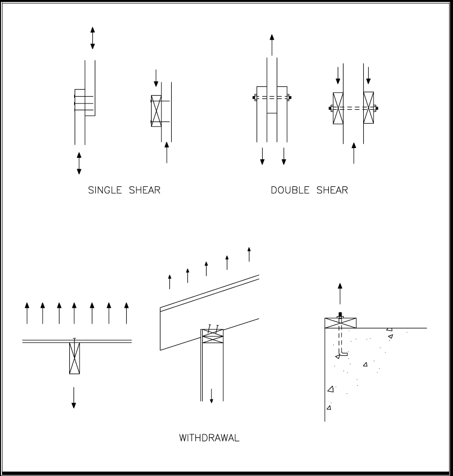
The NDS provides tabulated connection design values that use the following symbols for the three basic types of loading:
- W – withdrawal (or tension loading);
- Z⊥ – shear perpendicular to wood grain; and
- Z|| – shear parallel to wood grain.
In addition to the already tabulated design values for the structural resistance properties of connections described above, the NDS provides calculation methods to address conditions that may not be covered by the tables and that give more flexibility to the design of connections. The methods are appropriate for use in hand calculations or with computer spreadsheets.
For withdrawal, the design equations are relatively simple empirical relationships (based on test data) that explain the effect of fastener size (diameter), penetration into the wood, and density of the wood. For shear, the equations are somewhat more complex because of the multiple failure modes that may result from fastener characteristics, wood density, and size of the wood members. Six shear-yielding modes (and a design equation for each) address various yielding conditions in either the wood members or the fasteners that join the members. The critical yield mode is used to determine the design shear value for the connection.
The yield equations in the NDS are based on general dowel equations that use principles of engineering mechanics to predict the shear capacity of a doweled joint. The general dowel equations can be used with joints that have a gap between the members, and they can also be used to predict ultimate capacity of a joint made of wood, wood and metal, or wood and concrete. However, the equations do not account for friction between members, or the anchoring/cinching effect of the fastener head as the joint deforms and the fastener rotates or develops tensile forces. These effects are important to the ultimate capacity of wood connections in shear and, therefore, the general dowel equations may be considered conservative.
Adjusted Allowable Design Values
Design values for wood connections are subject to adjustments in a manner similar to that required for wood members themselves. The calculated or tabulated design values for W and Z are multiplied by the applicable adjustment factors to determine adjusted allowable design values, Z’ and W’, as shown below for the various connection methods (i.e., nails, bolts, and lag screws).
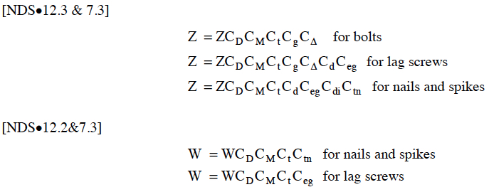
The adjustment factors and their applicability to wood connection design are briefly described as follows:
- CD – Load Duration Factor (NDS•2.3.2) – applies to W and Z values for all fasteners based on design load duration, but shall not exceed 1.6 (i.e., wind and earthquake load-duration factor).
- CM – Wet Service Factor (NDS•7.3.3) – applies to W and Z values for all connections based on moisture conditions at the time of fabrication and during service; not applicable to residential framing.
- Ct – Temperature Factor (NDS•7.3.4) – applies to the W and Z values for all connections exposed to sustained temperatures of greater than 100° F; not typically used in residential framing.
- Cg – Group Action Factor (NDS•7.3.6) – applies to Z values of two or more bolts or lag screws loaded in single or multiple shear and aligned in the direction of the load (i.e., rows).
- CΔ – Geometry Factor (NDS•8.5.2, 9.4.) – applies to the Z values for bolts and lag screws when the end distance or spacing of the bolts is less than assumed in the unadjusted design values.
- Cd – Penetration Depth Factor (NDS•9.3.3, 12.3.4) – applies to the Z values of lag screws and nails when the penetration into the main member is less than 8D for lag screws or 12D for nails (where D = shank diameter); sometimes applicable to residential nailed connections.
- Ceg – End Grain Factor (NDS•9.2.2, 9.3.4, 12.3.5) – applies to W and Z values for lag screws and to Z values for nails to account for reduced capacity when the fastener is inserted into the end grain (Ceg=0.67).
- Cdi – Diaphragm Factor (NDS•12.3.6) – applies to the Z values of nails only to account for system effects from multiple nails used in sheathed diaphragm construction (Cdi = 1.1).
- Ctn – Toenail Factor (NDS•12.3.7) – applies to the W and Z values of toe-nailed connections (Ctn = 0.67 for withdrawal and = 0.83 for shear). It does not apply to slant nailing in withdrawal or shear; refer to Section 7.3.6.
The total allowable design value for a connection (as adjusted by the appropriate factors above) must meet or exceed the design load determined for the connection. The values for W and Z are based on single fastener connections. In instances of connections involving multiple fasteners, the values for the individual or single fastener can be summed to determine the total connection design value only when Cg is applied (to bolts and lag screws only), and fasteners are the same type and similar size. However, this approach may overlook certain system effects that can improve the actual performance of the joint in a constructed system or assembly. Conditions that may decrease estimated performance, such as prying action induced by the joint configuration, and/or eccentric loads and other factors, should also be considered.
In addition, the NDS does not provide values for nail withdrawal or shear when wood structural panel members (i.e., plywood or oriented strand board) are used as a part of the joint. This type of joint (wood member to structural wood panel) occurs frequently in residential construction. Z values can be estimated by using the yield equations for nails in NDS 12.3.1 and assuming a reasonable specific gravity (density) value for the wood structural panels, such as G = 0.5. W values for nails in wood structural panels can be estimated in a similar fashion by using the withdrawal equation presented in the next section.
Nailed Connections
The procedures in NDS•12 provide for the design of nailed connections to resist shear and withdrawal loads in wood-to-wood and metal-to-wood connections. As mentioned, many specialty nail-type fasteners are available for wood-to-concrete and even wood-to-steel connections. The designer should consult manufacturer data for connection designs that use proprietary fastening systems.
The withdrawal strength of a smooth nail (driven into the side grain of lumber) is determined in accordance with either the empirical design equation below or NDS Table 12.2A.

The design strength of nails is greater when a nail is driven into the side rather than the end grain of a member. Withdrawal information is available for nails driven into the side grain; however, the withdrawal capacity of a nail driven into the end grain is assumed to be zero because of its unreliability. Furthermore, the NDS does not provide a method for determining withdrawal values for deformed shank nails. These nails significantly enhance withdrawal capacity and are frequently used to attach roof sheathing in high-wind areas. They are also used to attach floor sheathing and some siding materials to prevent nail back-out. The use of deformed shank nails is usually based on experience or preference.
The design shear value Z for a nail is typically determined by using the following tables from NDS•12:
- Tables 12.3A and B. Nailed wood-to-wood, single-shear (two-member) connections with the same species of lumber using box or common nails, respectively.
- Tables 12.3E and F. Nailed metal plate-to-wood connections using box or common nails, respectively.
The yield equations in NDS•12.3 may be used for conditions not represented in the design value tables for Z. Regardless of the method used to determine the Z value for a single nail, the value must be adjusted, as described in Section 7.3.2. As noted in the NDS, the single nail value is used to determine the design value.
It is also worth mentioning that the NDS provides an equation for determining allowable design value for shear when a nailed connection is loaded in combined withdrawal and shear. The equation appears to be most applicable to a gable-end truss connection to the roof sheathing under conditions of roof sheathing uplift and wall lateral load owing to wind. The designer might contemplate other applications but should take care in considering the combination of loads that would be necessary to create simultaneous uplift and shear worthy of a special calculation.
Bolted Connections
Bolts may be designed in accordance with NDS•8 to resist shear loads in wood-to-wood, wood-to-metal, and wood-to-concrete connections. As mentioned, many specialty bolt-type fasteners can be used to connect wood to other materials, particularly concrete and masonry. One common example is an epoxy-set anchor. Manufacturer data should be consulted for connection designs that use proprietary fastening systems.
The design shear value Z for a bolted connection is typically determined by using the following tables from NDS•8:
- Table 8.2A. Bolted wood-to-wood, single-shear (two-member) connections with the same species of lumber.
- Table 8.2B. Bolted metal plate-to-wood, single-shear (two-member) connections; metal plate thickness of 1/4-inch minimum.
- Table 8.2D. Bolted single-shear wood-to-concrete connections; based on minimum 6-inch bolt embedment in minimum fc = 2,000 psi concrete.
It should be noted that the NDS does not provide W values for bolts. The tension value of a bolt connection in wood framing is usually limited by the bearing capacity of the wood, as determined by the surface area of a washer used underneath the bolt head or nut. The bending capacity of the washer should be considered. For example, a wide but thin washer will not evenly distribute the bearing force to the surrounding wood.
The arrangement of bolts and drilling of holes are extremely important to the performance of a bolted connection. The designer should carefully follow the minimum edge, end, and spacing requirements of NDS•8.5.
Any possible torsional load on a bolted connection (or any connection, for that matter) should also be considered in accordance with the NDS. In such conditions, the pattern of the fasteners in the connection can become critical to performance in resisting both a direct shear load and the loads created by a torsional moment on the connection. Fortunately, this condition is not often applicable to typical light-frame construction. However, cantilevered members that rely on connections to anchor the cantilevered member to other members will experience this effect, and the fasteners closest to the cantilever span will experience greater shear load. One example of this condition sometimes occurs with balcony construction in residential buildings; failure to consider the effect discussed above has been associated with some notable balcony collapses.
For wood members bolted to concrete, the design lateral values are provided in NDS•Table 8.2 E. The yield equations (or general dowel equations) may also be used to conservatively determine the joint capacity.
Lag Screws
Lag screws (or lag bolts) may be designed to resist shear and withdrawal loads in wood-to-wood and metal-to-wood connections, in accordance with NDS•9. As mentioned, many specialty screw-type fasteners can be installed in wood. Some tap their own holes and do not require pre-drilling. Manufacturer data should be consulted for connection designs that use proprietary fastening systems.
The withdrawal strength of a lag screw (inserted into the side grain of lumber) is determined in accordance with either the empirical design equation below or NDS•Table 9.2A. It should be noted that the equation below is based on single lag screw connection tests and is associated with a reduction factor of 0.2 applied to average ultimate withdrawal capacity to adjust for load duration and safety. Also, the penetration length of the lag screw Lp into the main member does not include the tapered portion at the point.

The allowable withdrawal design strength of a lag screw is greater when the screw is installed in the side rather than the end grain of a member. However, unlike the treatment of nails, the withdrawal strength of lag screws installed in the end grain may be calculated by using the Ceg adjustment factor with the equation above.
The design shear value Z for a lag screw is typically determined by using the following tables from NDS•9:
- Table 9.3A. Lag screw, single-shear (two-member) connections with the same species of lumber for both members.
- Table 9.3B. Lag screw and metal plate-to-wood connections.
The yield equations in NDS•9.3 may be used for conditions not represented in the design value tables for Z. Regardless of the method used to determine the Z value for a single lag screw, the value must be adjusted.
System Design Considerations
As with any building code or design specification, the NDS provisions may or may not address various conditions encountered in the field. There may be alternative or improved design approaches. Similarly, some considerations regarding wood connection design are appropriate to address here.
First, as a general design consideration, crowded connections should be avoided. If too many fasteners are used (particularly nails), they may cause splitting during installation. When connections become crowded, an alternative fastener or connection detail should be considered. Basically, the connection detail should be practical and efficient.
Second, while the NDS addresses system effects within a particular joint (i.e., element) that uses multiple bolts or lag screws (i.e. the group action factor Cg), it does not include provisions regarding the system effects of multiple joints in an assembly or system of components. Therefore, some consideration of system effects is given below based on several relevant studies related to key connections in a home that allow the dwelling to perform effectively as a structural unit.
Sheathing Withdrawal Connections
Several past studies have focused on roof sheathing attachment and nail withdrawal, primarily as a result of Hurricane Andrew (HUD, 1999a; McClain, 1997; Cunningham, 1993; Mizzell and Schiff, 1994; and Murphy, Pye, and Rosowsky, 1995). The studies identify problems related to predicting the pull-off capacity of sheathing based on single-nail withdrawal values and determining the tributary withdrawal load (i.e., wind suction pressure) on a particular sheathing fastener. One clear finding, however, is that the nails on the interior of the roof sheathing panels are the critical fasteners (i.e., initiate panel withdrawal failure) because of the generally larger tributary area served by these fasteners. The studies also identified benefits of the use of screws and deformed shank nails. However, the use of a standard geometric tributary area of the sheathing fastener and the wind loads, along with the NDS withdrawal values, will generally result in a reasonable design using nails. The wind-load duration factor should also be applied to adjust the withdrawal values, since a commensurate reduction is implicit in the design withdrawal values relative to the short-term, tested and ultimate withdrawal capacities.
It is interesting to note, however, that one study found that the lower-bound (i.e., 5th percentile) sheathing pull-off resistance was considerably higher than that predicted by the use of single-nail test values (Murphy, Pye and Rosowsky, 1995). The difference was as large as a factor of 1.39 greater than the single-nail values. While this would suggest a withdrawal system factor of at least 1.3 for sheathing nails, it should be subject to additional considerations. For example, sheathing nails are placed by people using tools in somewhat adverse conditions (i.e., on a roof), and not in a laboratory. Therefore, this system effect may be best considered as a reasonable construction tolerance on actual nail-spacing variation relative to that intended by design. Thus, an 8- to 9-inch nail spacing on roof sheathing nails in the panel’s field could be tolerated when a 6-inch spacing is targeted by design.
Roof-to-Wall Connections
A couple of studies have investigated the capacity of roof-to-wall (i.e., sloped rafter-to-top plate) connections using conventional toe-nailing and other enhancements (i.e., strapping, brackets, gluing, etc.). Again, the primary concern is related to high wind conditions, such as those experienced during Hurricane Andrew and other extreme wind events.
First, as a matter of clarification, the toenail reduction factor Ctn does not apply to slant-nailing, such as those used for rafter-to-wall connections and floor-to-wall connections in conventional residential construction. Toe-nailing occurs when a nail is driven at an angle in a direction parallel to the grain at the end of a member (i.e., a wall stud toenail connection to the top or bottom plate that may be used instead of end nailing). Slant nailing occurs when a nail is driven at an angle, but in a direction perpendicular to the grain through the side of the member and into the face grain of the other (i.e., from a roof rafter or floor band joist to a wall top plate). Though this is a generally reliable connection in most homes and similar structures built in the United States, even a well-designed slant-nail connection used to attach roofs to walls is impractical in hurricane-prone regions or similar high-wind areas. In these conditions, a metal strap or bracket is preferable.
Based on the studies of roof-to-wall connections, five key findings are summarized as follows (Reed et al., 1996; Conner et al., 1987):
- In general, it was found that slant-nails (not to be confused with toenails) in combination with metal straps or brackets do not provide directly additive uplift resistance.
- A basic metal twist strap placed on the interior side of the walls (i.e., gypsum board side) resulted in top plate tear-out and premature failure. However, a strap placed on the outside of the wall (i.e., structural sheathing side) was able to develop its full capacity without additional enhancement of the conventional stud-to-top plate connection (see Table 1).
- The withdrawal capacity for single joints with slant nails was reasonably predicted by NDS with a safety factor of about 2 to 3.5. However, with multiple joints tested simultaneously, a system factor on withdrawal capacity of greater than 1.3 was found for the slant-nailed rafter-to-wall connection. A similar system effect was not found on strap connections, although the strap capacity was substantially higher. The ultimate capacity of the simple strap connection (using five 8d nails on either side of the strap–five in the spruce rafter and five in the southern yellow pine top plate) was found to be about 1,900 pounds per connection. The capacity of three 8d common slant nails used in the same joint configuration was found to be 420 pounds on average, and with higher variation. When the three 8d common toenail connection was tested in an assembly of eight such joints, the average ultimate withdrawal capacity per joint was found to be 670 pounds, with a somewhat lower variation. Similar system increases were not found for the strap connection. The 670-pound capacity was similar to that realized for a rafter-to-wall joint using three 16d box nails in Douglas fir framing.
- It was found that the strap manufacturer’s published value had an excessive safety margin of greater than 5 relative to average ultimate capacity. Adjusted to an appropriate safety factor in the range of 2 to 3 (as calculated by applying NDS nail shear equations by using a metal side plate), the strap (a simple 18g twist strap) would cover a multitude of high-wind conditions with a simple, economical connection detail.
- The use of deformed shank (i.e., annular ring) nails was found to increase dramatically the uplift capacity of the roof-to-wall connections using the slant nailing method.
Heel Joint in Rafter-to-Ceiling Joist Connections
The heel joint connection at the intersection of rafters and ceiling joists has long been considered one of the weaker connections in conventional wood roof framing. In fact, this highly stressed joint represents one of the significant reasons for using a wood truss, rather than conventional rafter framing (particularly in high-wind or snow-load conditions). However, the performance of conventional rafter-ceiling joist heel-joint connections should be understood by the designer, since they are frequently encountered in residential construction.
First, conventional rafter and ceiling joist (cross-tie) framing is simply a site-built truss. Therefore, the joint loads can be analyzed by using methods that are applicable to trusses (i.e., pinned joint analysis). However, the performance of the system should be considered. As mentioned earlier for roof trusses, a system factor of 1.1 is applicable to tension members and connections. Therefore, the calculated shear capacity of the nails in the heel joint (and in ceiling joist splices) may be multiplied by a system factor of 1.1, which is considered conservative. Second, it must be remembered that the nail shear values are based on a deformation limit, and generally have a conservative safety factor of 3 to 5, relative to the ultimate capacity. Finally, the nail values should be adjusted for duration of the load (i.e., snow load duration factor of 1.15 to 1.25). With these considerations and with the use of rafter support braces at or near mid-span (as is common), reasonable heel joint designs should be possible for most typical design conditions in residential construction.
Wall-to-Floor Connections
When wood sole plates are connected to wood floors, many nails are often used, particularly along the total length of the sole plate or wall bottom plate. When connected to a concrete slab or foundation wall, there are usually several bolts along the length of the bottom plate. This points toward the question of possible system effects in estimating the shear capacity (and uplift capacity) of these connections for design purposes.
In recent shear wall tests, walls connected with pneumatic nails (0.131-inch diameter by 3 inches long) spaced in pairs at 16 inches on center along the bottom plate were found to resist over 600 pounds in shear per nail. The bottom plate was spruce-pine-fir lumber and the base beam was southern yellow pine. This value is about 4.5 times the adjusted allowable design shear capacity predicted by use of the NDS equations. Similarly, connections using 5/8-inch-diameter anchor bolts at 6 feet on center (all other conditions equal) were tested in full shear wall assemblies; the ultimate shear capacity per bolt was found to be 4,400 pounds. This value is about 3.5 times the adjusted allowable design shear capacity, per the NDS equations. These safety margins appear excessive and should be considered by the designer when evaluating similar connections from a practical system standpoint.
Design of Concrete and Masonry Connections
General
In typical residential construction, the interconnection of concrete and masonry elements or systems is generally related to the foundation and usually handled in accordance with standard or accepted practice. The bolted wood member connections to concrete are suitable for bolted wood connections to properly grouted masonry. Moreover, numerous specialty fasteners or connectors (including power-driven and cast-in-place) can be used to fasten wood materials to masonry or concrete. The designer should consult the manufacturer’s literature for available connectors, fasteners, and design values.
Concrete or Masonry Foundation Wall to Footing
Footing connections, if any, are intended to transfer shear loads from the wall to the footing below. The shear loads are generally produced by lateral soil pressure acting on the foundation.
Footing-to-wall connections for residential construction are constructed in any one of the following three ways (refer to Figure 5 for illustrations of the connections):
- no vertical reinforcement or key;
- key only; or
- dowel only.
FIGURE 5. Concrete or Masonry Wall-to-Footing Connections
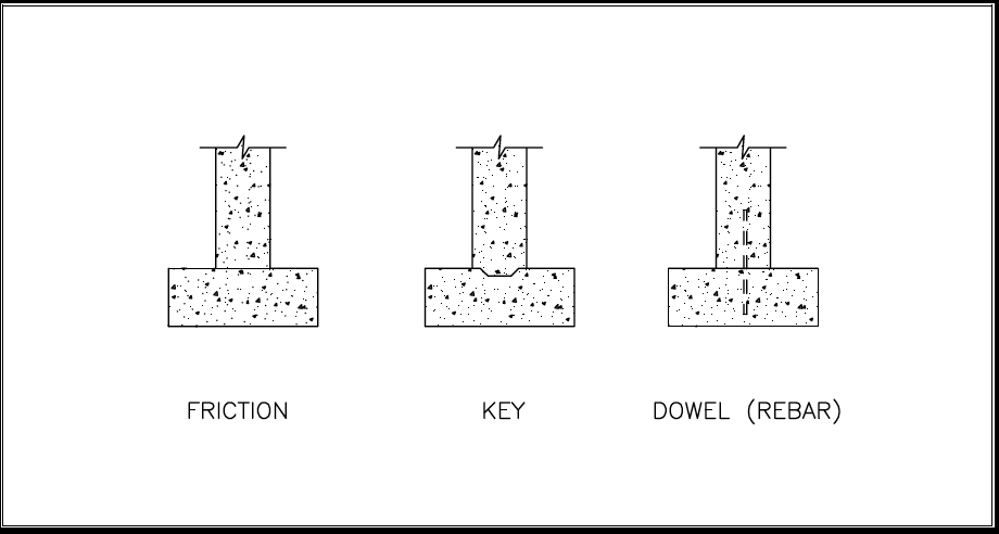
Friction Used to Provide Shear Transfer
To verify the amount of shear resistance provided by friction alone, assume a coefficient of friction between two concrete surfaces of μ = 0.6. Using dead loads only, determine the static friction force, F =μ NA, where F is the friction force (in pounds), N is the dead load (psf), and A is the bearing surface area (in square feet) between the wall and the footing.
Key Used to Provide Shear Transfer
A concrete key is commonly used to interlock foundation walls to footings. If foundation walls are constructed of masonry, the first course of masonry must be grouted solid when a key is used.
In residential construction, a key is often formed by using a 2x4 wood board with chamfered edges that is placed into the surface of the footing immediately after the concrete pour. Figure 6 illustrates a footing with a key. Shear resistance developed by the key is computed in accordance with the equation below.
FIGURE 6. Key in Concrete Footings

Dowels Used to Provide Adequate Shear Transfer
Shear forces at the base of exterior foundation walls may require a dowel to transfer the forces from the wall to the footing. The equations below, described by ACI-318 as the Shear-Friction Method, are used to develop shear resistance with vertical reinforcement (dowels) across the wall-footing interface.
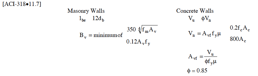
If dowels are used to transfer shear forces from the base of the wall to the footing, use the equations below to determine the minimum development length required (refer to Figure 7 for typical dowel placement). If development length exceeds the footing thickness, the dowel must be in the form of a hook, which is rarely required in residential construction.
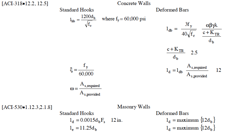
FIGURE 7. Dowel Placement in Concrete Footings
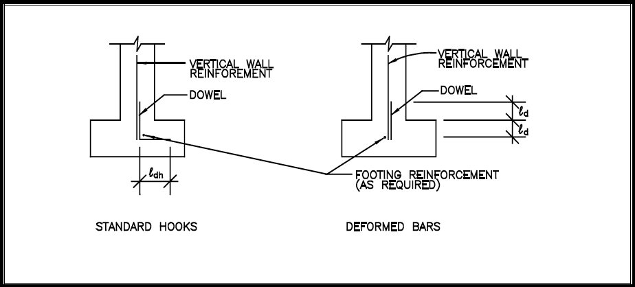
The minimum embedment length is a limit specified in ACI-318 that is not necessarily compatible with residential construction conditions and practice. Therefore, this guide suggests a minimum embedment length of 6 to 8 inches for footing dowels, when necessary, in residential construction applications. In addition, dowels are sometimes used in residential construction to connect other concrete elements, such as porch slabs or stairs, to the house foundation to control differential movement. However, exterior concrete flatwork adjacent to a home should be founded on adequate soil bearing or reasonably compacted backfill. Finally, connecting exterior concrete work to the house foundation requires caution, particularly in colder climates and soil conditions where frost heave may be a concern.
The minimum embedment length is a limit specified in ACI-318 that is not necessarily compatible with residential construction conditions and practice. Therefore, this guide suggests a minimum embedment length of 6 to 8 inches for footing dowels, when necessary, in residential construction applications. In addition, dowels are sometimes used in residential construction to connect other concrete elements, such as porch slabs or stairs, to the house foundation to control differential movement. However, exterior concrete flatwork adjacent to a home should be founded on adequate soil bearing or reasonably compacted backfill. Finally, connecting exterior concrete work to the house foundation requires caution, particularly in colder climates and soil conditions where frost heave may be a concern.
Anchorage and Bearing on Foundation Walls
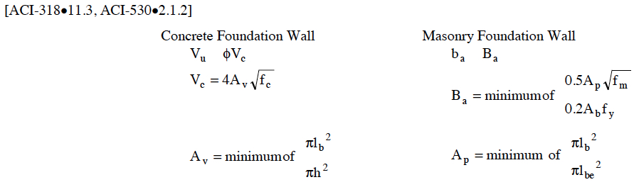
Anchorage Tension (Uplift) Capacity
The equations below determine whether the concrete or masonry shear area of each bolt is sufficient to resist pull-out from the wall as a result of uplift forces and shear friction in the concrete.
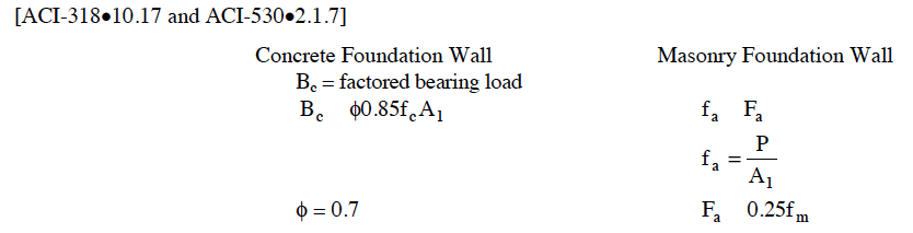
Bearing Strength
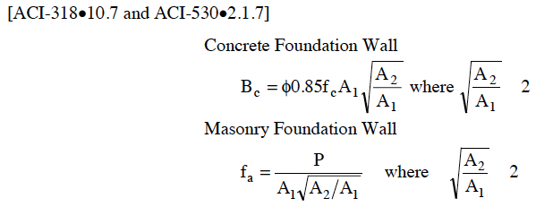
Determining the adequacy of the bearing strength of a foundation wall follows ACI-318•10.17 for concrete or ACI-530•2.1.7 for masonry. The bearing strength of the foundation wall is typically adequate for the loads encountered in residential construction.
When the foundation wall’s supporting surface is wider on all sides than the loaded area, the designer is permitted to determine the design bearing strength on the loaded area by using the equations below.
Summary
The information in this article serves as a resource for both inspectors and designers who work with structural connections, and how these connections:
- transfer loads resisted by structural members and systems to other parts of the structure to form a continuous load path;
- secure non-structural components and equipment to the building; and
- fasten members in place during construction to resist temporary loads during installation.

Structural Design Concepts for the Home Inspector
Structural Design Loads for the Home Inspector
Structural Design of Foundations for the Home Inspector
Structural Design of Lateral Resistance to Wind and Earthquake for the Home Inspector
Structural Design of Wood Framing for the Home Inspector
Take InterNACHI's free, online "Structural Issues for Home Inspectors" course.
Take InterNACHI's free, online "Inspecting Foundation Walls and Piers" course.
Take InterNACHI's free, online "How to Inspect for Moisture Intrusion" course.