It looks to me like since both feeders are on the same bus bar and that it looks like both bus bars are connected (maybe I’m wrong) each conductor is carrying 220v to the sub-panel served by this service panel. Shouldn’t they be on separate bus bars so that they can serve 120v circuits?
Or does this mean that both bus bars are not connected and each feeder is only carrying 120v? It looks like the copper bus bar on the right is connected to the main disconnect, but I don’t know why it would be energized unless the two bus bars are connected by the lug devices.
At the top right, does the metal strap at the top of the neutral bus bar go up and connect to another lug to which the neutral service entrance conductor is attached?
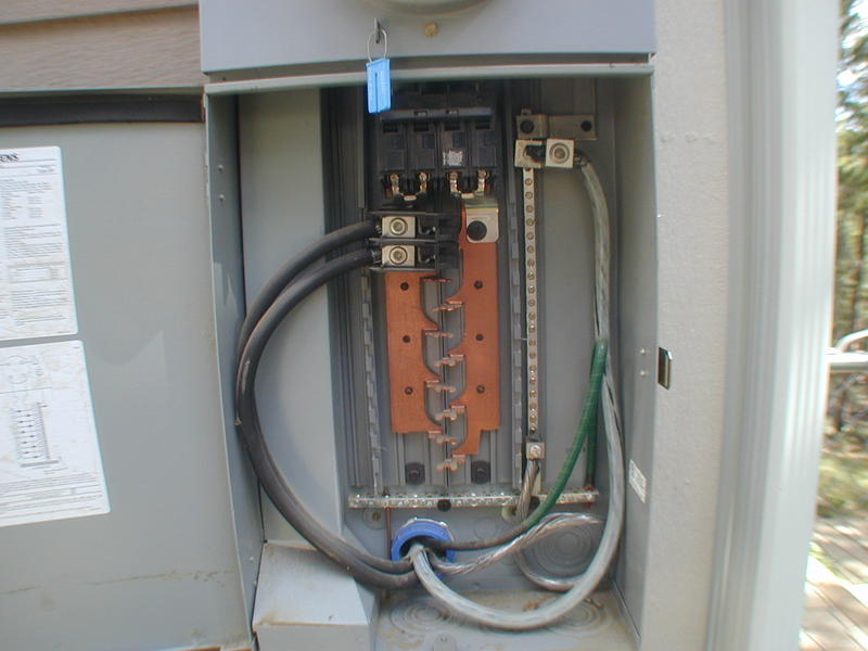
If that’s the main panel, wouldn’t the green wrapped conductor just be the GEC perhaps connecting down to a ufer or waterpipe? That would make the other two on the bus bar at the right the grounding conductor and the grounded conductor(neutral) feeding the subpanel.
Looks to me like the feeder is attached to both buses using a special connector which means that it’s protected by the main CB and yielding 120/240 volts. The green GEC run in the connector with the feeder is questionable as is the large lug terminating the neutral near the top.
I would say they’re separate, 120V each. Looks like just the service disconnect.
- There are two feeders, and if they’re both attached to both bus bars, aren’t they both carrying 240v? Maybe they’re actually connected to separate bus bars?
- Green I’m assuming is the GEC. It’s bonded to the neutral feed which seems fine to me in a service panel.
- Bare aluminum is neutral feed to the subpanel
- Where’s the SEC neutral connection?
Look carefully at the tangs on those bus bars Kenton.
It should make sense then.
The SEC for the neutral is the only thing I don’t see. I assume the service entrance conductors are coming in from the top above the main breaker?
Upper right hand corner. The strap going up.
Right, there’s a flat metal strap that disappears in to the cabinet above that looks like it probably serves as the connection, I’ve just never seen that method used and want to confirm that’s the SEC connection.
1-not sure what you mean by two feeders? The feeder is a 120/240 volt MWBC.
2-There are two GEC’s the one taped green probably for the water main and the bare one from the ground rod(s).
3-Bare Al is not the neutral but the EGC in the SER cable feeder.
4-Looks like a for use only as service equipment panel which has the neutral factory bonded to the enclosure.
Mike, if you know, can you please just explain.
The connection tangs alternate between the two 120 v legs and they go down the bus bar.
Those two connection lugs are not on the same leg.

Yep, thank you, the measurements are about right.
That is a meter/main combo with a lug kit installed to supply the panel on the inside. The cable going through is a four wire cable and the green is probably a grounding electrode conductor.
Although it looks like both conductors are on the bus bar to the left it is hitting both bus bars.
You seem to be referring to one single cable and calling it a 4-wire cable. I don’t understand. Please remember that this is not an electrical MB like Mike Holt, and a lot of us are not going to understand terms that electrical contractors take for granted.
Pretty standard manufactured home set-up.
The service disconnect is the horizontal breaker at the top of the panel. As Mike Whitt said, the “lug kit” supplies a sub panel, which is likely built in to the manufactured home (I usually see them inside an attached garage).
I understood those basics from the beginning, although I didn’t know this was typical of a manufactured home. It was the feeder and neutral connections that I wans’t sure about.
Why is this typical of a manufactured home? What’s different?
Manufactured homes have disconnect outside with a panel inside treated as a sub fed with a 4 wire feeder.
There is only one feeder, it’s the four wire SER cable (two blacks, one white, one bare) that exits at the bottom left. The additional taped green conductor is a GEC that they ran through the same connector as the SER cable.
The SER cable is terminated with the:
-two blacks on the bus as the hot legs,
-the white on the neutral bus on the top right as the neutral and
-the bare on the neutral bus as the EGC in the SER cable feeder to the subpanel.