Observation
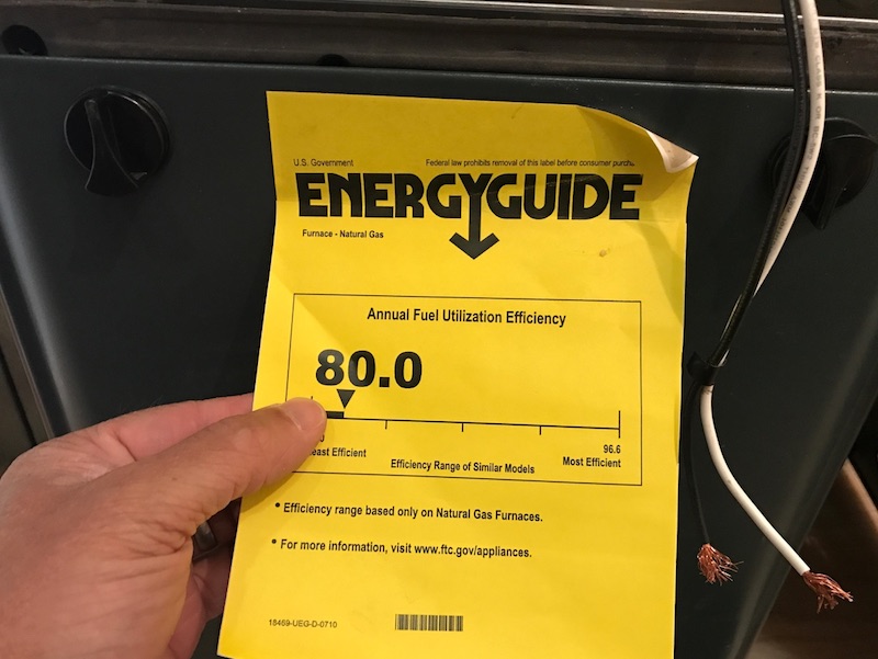
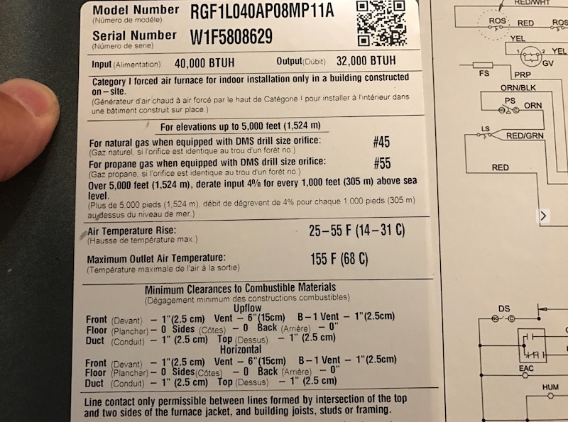
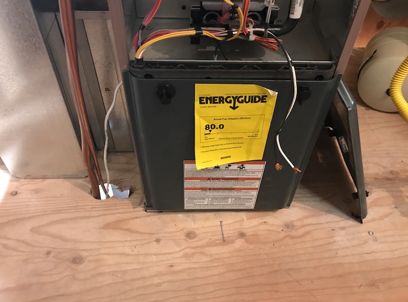
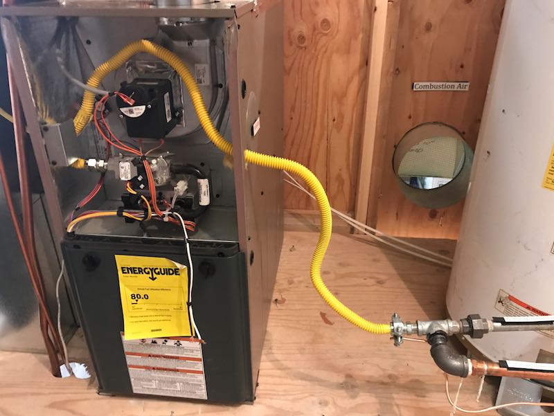
The furnace is 80% efficient. You may calculate the efficiency by dividing output BTU by input BTU on the manufacturer's data sticker. Or, there may be an efficiency sticker attached, such as the yellow sticker.
Heating and cooling equipment and appliances must be accessible for inspection, routine maintenance, repairs and replacements.

Observation
There are combustible wall materials in close proximity to the gas-fired furnace appliance. According to the manufacturer, the minimum clearance from the back-side of the appliance is 0 inches.

Observation
There's no condensate drainage or pump installed for the central air conditioner's evaporator.
Observation
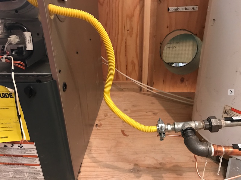
The combustion air opening at the exterior wall of the furnace room may cause pipe freezing problems for cold climates.

Observation
There are 2 air registers on the exterior of the house, on the wall opposite the furnace room. One is blocked with debris.

Observation
The combustion air opening at the exterior wall of the furnace room may cause pipe freezing problems for cold climates.

Observation
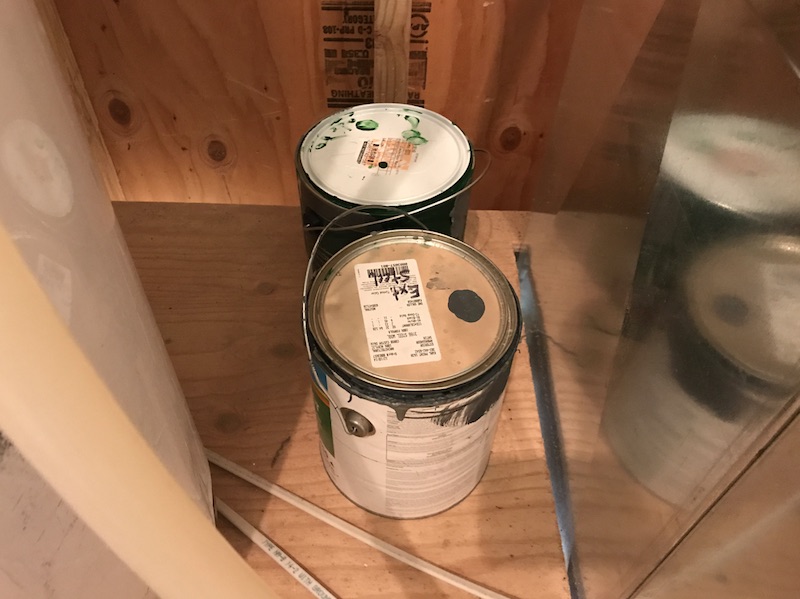
There are cans of chemicals in the utility room. They should be removed to help prevent corrosion of the HVAC system.
Observation
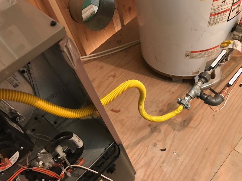
Unconventional installation of the fuel supply pipes, materials, components, valves, and support at the furnace and water heater tank.

Observation
There is not a sediment trap installed. Defect.
Observation
There is no shutoff valve installed.
FLEXIBLE GAS CONNECTORS vs. CSST
Observation
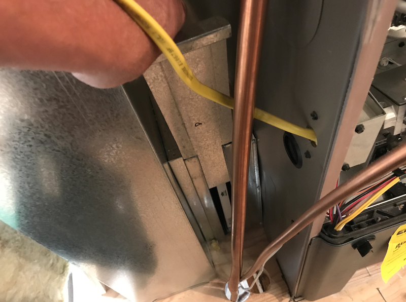
The flexible gas line should not be installed within the furnace cabinet. Only solid gas piping should be connected to and installed within the cabinet.

Observation
The flexible gas line is extremely bent within the cabinet and is possibly damaged, but his flexible line should not be installed within the cabinet.
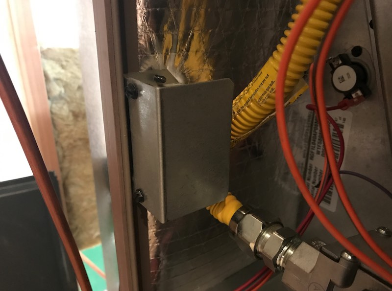
Observation
There is not a union fitting installed.

Observation
There is inadequate support for the fuel pipes.
Observation
The gas vent pipe from the water heater tank is improperly sloped. There is a disconnection at the elbow. This vent pipe is connected to the shared vent stack with the furnace.

Cloth duct tape is not permitted to be installed on fuel-burning appliance vent pipes. Many municipalities do not allow metal foil tape either.

Single wall vent pipe must be connected with 3 sheet metal screws at each joint.
Single wall flue vents require a six-inch minimum of clearance to combustibles, and B-vent (double wall) requires minimum 1-inch clearance.
Observation
There is no insulation shield installed in the attic around the flue vent pipe.
Observation
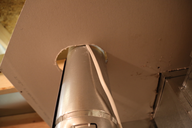
Electrical cable is in contact with the vent pipe of the furnace.
Observation
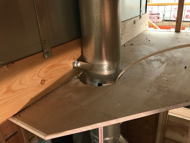
Missing fireblocking at the furnace vent chimney pipe where it penetrates the ceiling of the furnace room.

Observation
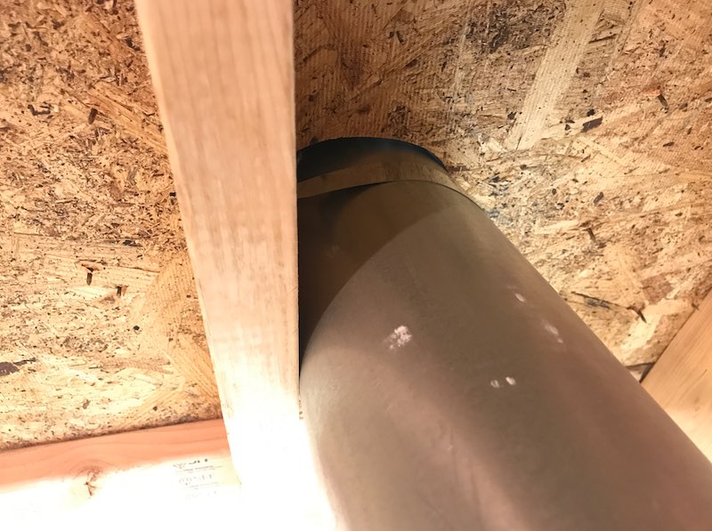
Inadequate clearance from combustibles at the gas vent stack for the furnace at the drywall and wooden structural components.
The clearance between gas vents and combustible materials is listed by the manufacturer, but is typically 1 inch for Type B.
Observation
The gas vent violates the required clearance from the nearly vertical obstruction.

Observation
There is a missing vent cap at the furnace gas vent (chimney).
Observation
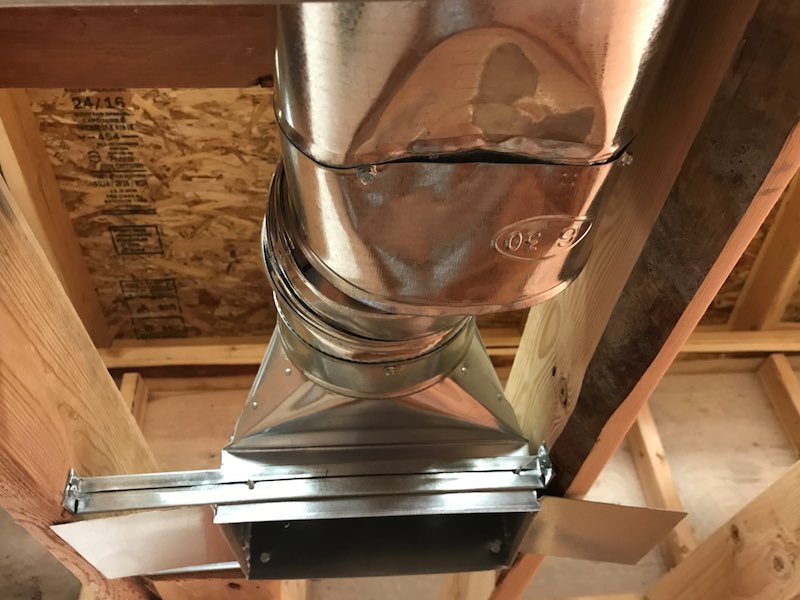
The opening between the duct and the floor sheathing creates an opening to the unconditioned crawlspace.

Observation
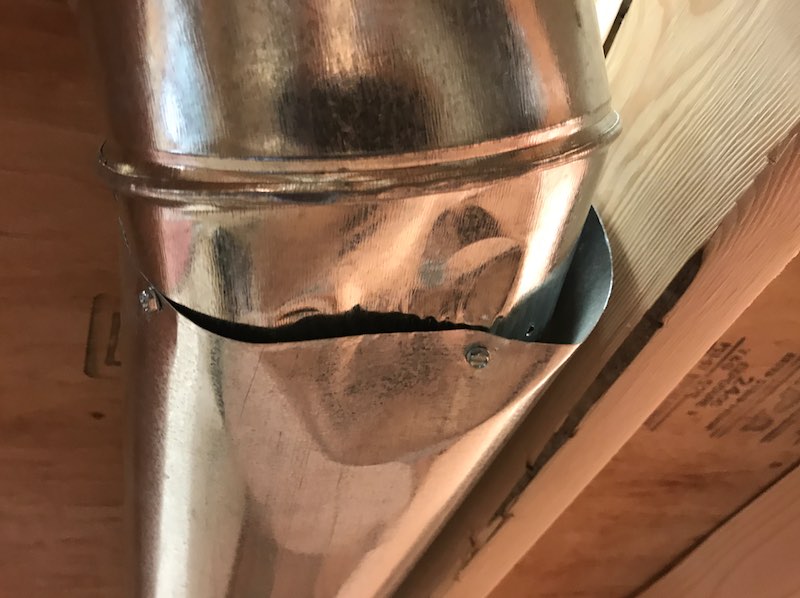
There is a crushed and damaged duct pipe in the ceiling of the kitchen.
Observation

Observation

Observation

Observation
The round duct pipe in the ceiling is not sized correctly, and there is a large opening and loose connection.
Observation

Observation
There is loose connection at the duct to the right of the water heater tank.

Observation

Observation
Duct should not be used for supporting pipes.

Observation
Ducts are not air sealed.

Observation
There is an open HVAC duct located on the rear wall of the garage.
According to the International Residential Code 2015 M1601.6 Independent Garage HVAC Systems, furnaces or air-handling systems that supply air to living spaces shall not supply air to or return air from a garage. Circulation of air contaminated with objectionable odors, flumes or flammable vapors is prohibited because of potential health and safety hazards.

Observation
There is metal duct in the crawlspace that is not securely fastened. There are sections of duct that are loose to the touch.

Observation
The flexible duct in the crawlspace is not supported adequately.

Observation
The metal duct in the crawlspace is not supported improperly, and it does not seem reliable.

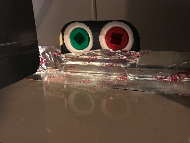
The joints, seams and connections in metallic and non-metalllic ducts must be securerly fastened and sealed with welds, gaskets, mastics, liquid sealants, or tapes. Tapes and mastics should be listed and marked with "UL 181 A-P" for tape, "181 A-M" for mastic or "181 A-H" for heat-sensitive tape.

"181 B-FX" is for flexible ducts. Crimp joints for round metallic jucts should have a 1-inch lap and at least 3 sheet-metal screws or rivets at the joint.
Ducts require adequate support at regular intervals.
Observation
The ducts in unconditioned spaces, including the crawlspace and attic, are not insulated.

Observation
The vibration material observed above the furnace is stretched tightly without any room for movement and flexibility.

Observation
The vibration material observed from the attic space should not be located there. This vibration material should be accessible for easy inspection and service, if needed. The vibration material is very tight and has no material for flexibility.

Observation
Clearances for supply plenum and ducts to combustible materials are in accordance to manufacturer's instructions and typically apply within 3' of central heating furnace. Typical clearance where applicable is one inch.

Observation
There should not be a return duct register installed in the kitchen.

There is an exception at 2017 IRC M1602.2 where there's at least 10 feet of clearance from a cooking appliance and the opening serves the kitchen only.
Observation
There should not be a return duct register installed in the furnace room, particularly when there's competition for air with the clothes dryer and natural-draft water heater tank. Hazardous back-drafting could result.

Observation
The return register at the duct to the left of the furnace and at the ceiling is within 10 feet of the draft hood of the water heater tank located in the same space as the return register.

Observation

Observation
The electrical shutoff switch for the furnace has a fuse device. Fuses are antiquated.

Observation
The electric receptacle is missing a clamp at the top of the electrical box.

Observation
The electric wiring to the furnace cabinet is not properly installed, loose and not secure, and is missing a clamp connection to the cabinet.

Observation
There is a loose wire connection at the controls of the furnace, near the burner control component.

Observation
The air filter is not accessible. The refrigerant lines block the filter access location.
Observation
The condensate drain lines and condensate pump are not installed.
Observation
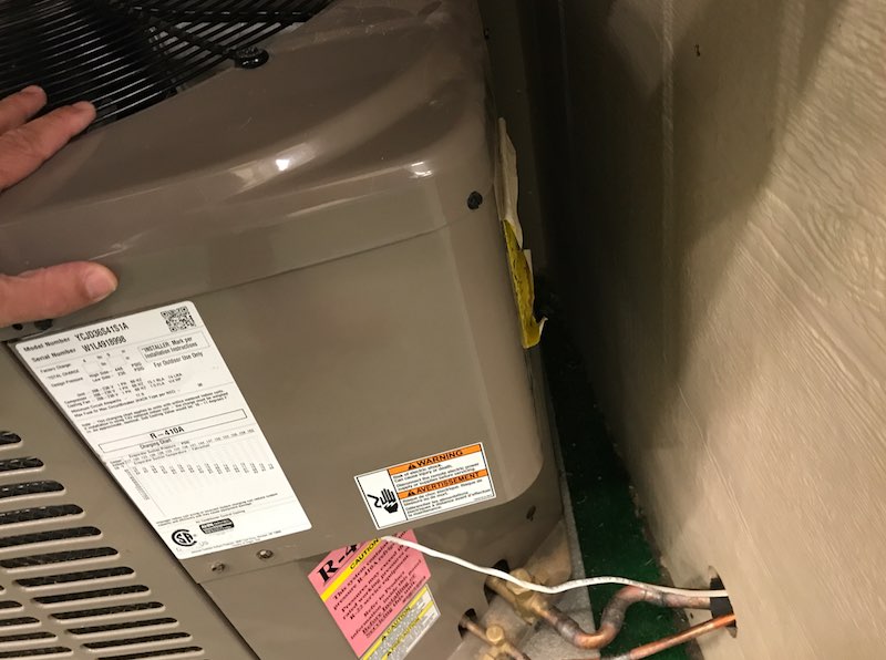
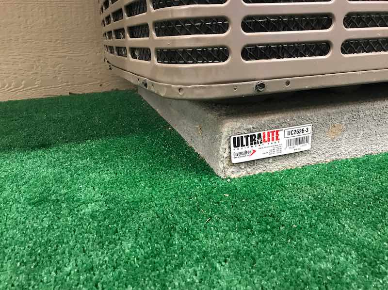
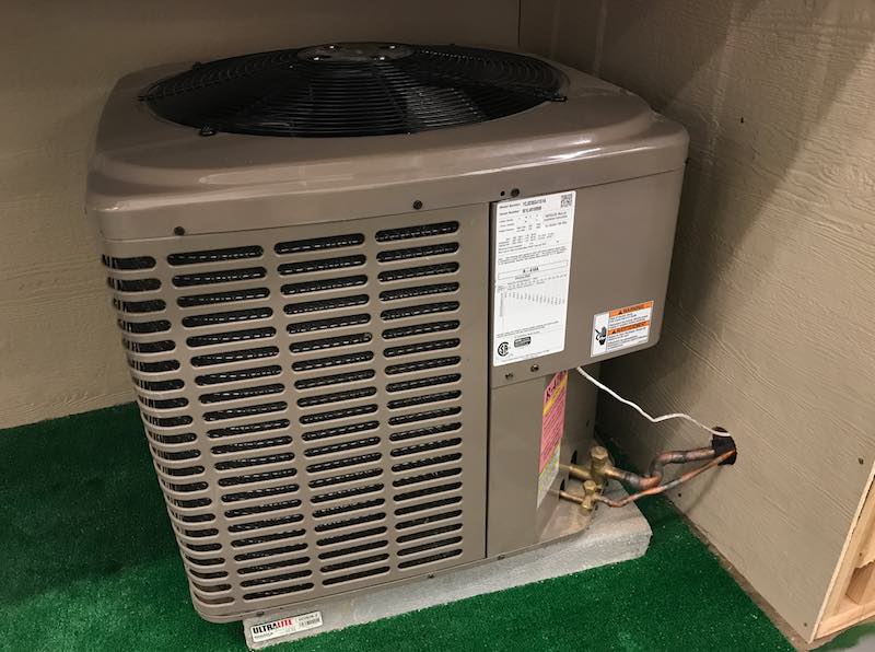
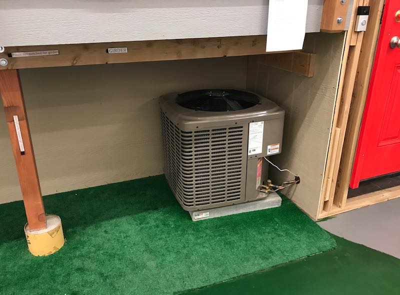
The unit appears to be off-center of its support base.
Observation
Inadequate clearance between the air conditioner's outdoor compressor unit and the house and deck structures.
Observation
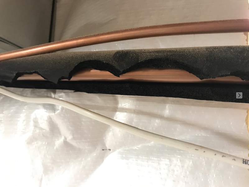
The pipes for the refrigerant vapor (suction) line should be insulated with at least an R-4 value. line should be insulated with at least an R-4 value")
Observation
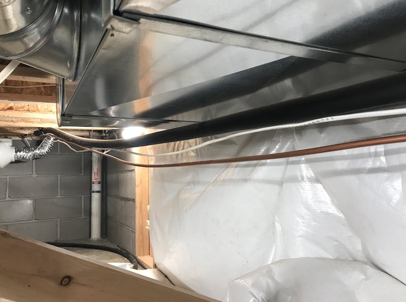
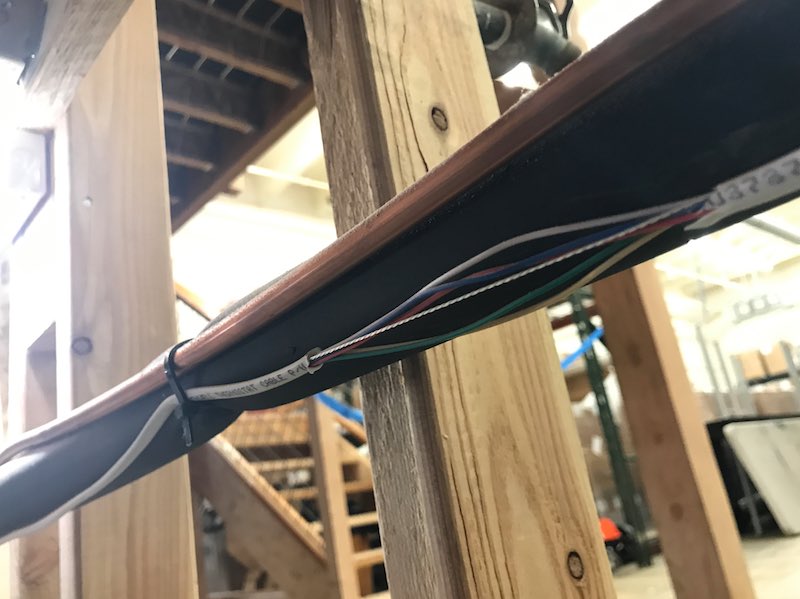
The refrigerant lines are improperly attached to and supported by the ductwork.

Observation
The refrigerant lines in the crawlspace are inadequately supported. They are hanging.
Observation
There is a large open hole in the siding through which the refrigerant lines pass. This hole should be sealed to prevent vermin entry and moisture intrusion. 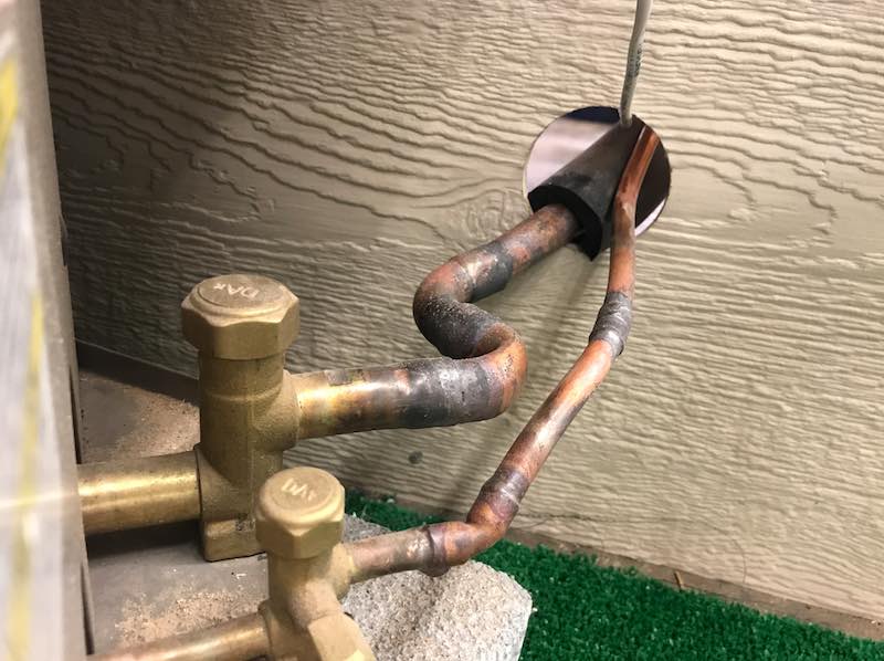
Observation
There's a squeezed, damaged area of the refrigerant line located near the air filter of the furnace. 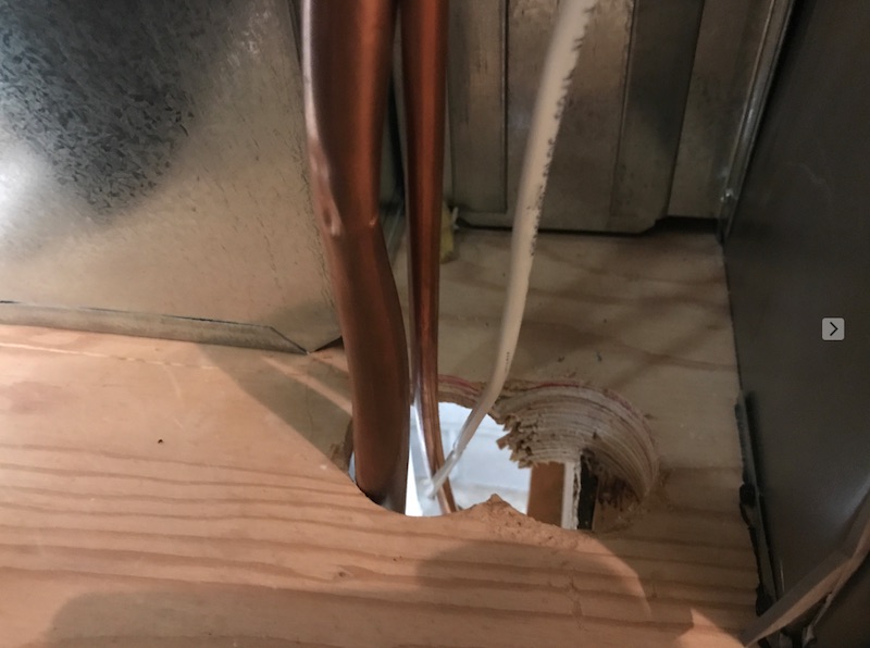
Observation
There's no slack in the refrigerant lines.

Observation
There are sections of pipe foam insulation on the suction line. There are damaged insulation in areas.
Observation
The electrical disconnect is missing. According to NEC 440.14, there should be a electrical disconnect within sight and readily accessible of the air conditioning unit.
Observation
The low-voltage line for the air conditioner system is damaged as observed from the crawlspace.
Observation
There should be an GFCI-protected electric receptacle installed located within 25 feet of the air conditioner outdoor unit and on the same level as the equipment.
There is no exterior receptacle properly installed.