How to Inspect the Skylight Shaft Wall Insulation
by Nick Gromicko, CMI® and Ben Gromicko
When skylights are installed, attention should be paid
to how the vertical shafts extending from the roof to the ceiling are insulated.
Unsealed attics are often insulated along the attic floor with blown fiberglass
or cellulose insulation. A different type of insulation will need to be
installed along the skylight shaft walls, one that will maintain both the full alignment
(or contact) with the back side of the sheathing for the height of the skylight
shaft walls and at least the minimum required depth of
insulation along the full height. Skylight shaft walls should be insulated to
the same R-value as other exterior walls if the attic they pass through is not
insulated.

The above illustration shows the components of a skylight shaft with properly installed insulation material. Enlarge illustration.
There are several options for insulating skylight shafts.
One option to consider, especially if several skylights are being installed, is
to insulate the entire attic by spray foaming along the underside of
the roofline, by installing rigid foam above the roof deck, or by constructing
the roof with structural insulated panels (SIPs). This insulated attic would
also provide a conditioned space for any HVAC equipment installed there.
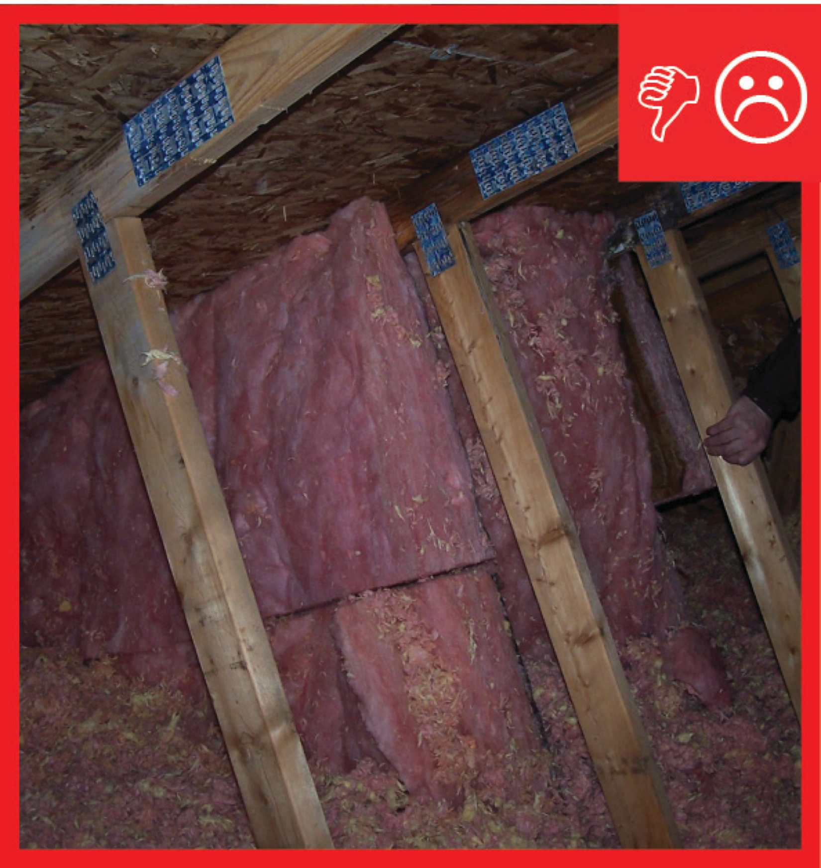
If the skylight shafts are installed in a vented, uninsulated attic, then the sides of the skylight shaft should be insulated. This can be accomplished using spray foam or rigid foam, or by constructing the shaft walls with SIPs. Fiberglass batt insulation is not recommended for insulating the skylight shaft walls because it can settle or pull away from the wall. If batt insulation is used, it should be covered with a rigid material, such as rigid foam, which will provide an interior air barrier and ensure that the batts will not slide down or fall away from the wall.

The image above shows a skylight shaft with fiberglass batt insulation installed, but there is a missing cover of rigid material, which would help prevent settlement and provide an air barrier.
These rigid materials may
be installed by insulators, framers, or subcontractors or vendors hired
specifically to install the skylight. This task should be included in the
contract for the appropriate trade, depending on the workflow at the specific
job site.
How to Insulate a Skylight Shaft
- Select the skylight size and location to avoid cutting roof or ceiling rafters, if possible. (House designs that use 24-inch, on-center, fully aligned framing members are less likely to require cutting of studs for skylight installation.) Follow the manufacturer’s instructions to install the skylight on the roof deck, properly flashing and integrating the skylight frame with roofing materials to minimize the risk of water intrusion. The roof opening is framed with headers, with framing lumber run horizontally across the opening and securely nailed to the rafters to support the structure.
- Install headers across the ceiling opening as you did for the roof opening, using a single header at each end if no ceiling joists are cut, or double headers if a ceiling joist has to be cut. If the light shaft will be flared, cut the joist at the angle of the flare.
- Cut 2x4 studs (or 2x6 to allow for more cavity insulation) for the corners of the light shaft, angled on each end to fit flush against the rafters and ceiling joists. Next, place the studs 24 inches on-center around the opening. Nail 2x2 cleats to the inside edges of the corner studs, or use drywall clips to serve as backing for the drywall.
Or,
Frame the shaft with structural insulated panels (SIPs)
following the manufacturer’s instructions for air sealing the corners, seams,
and top and bottom edges.
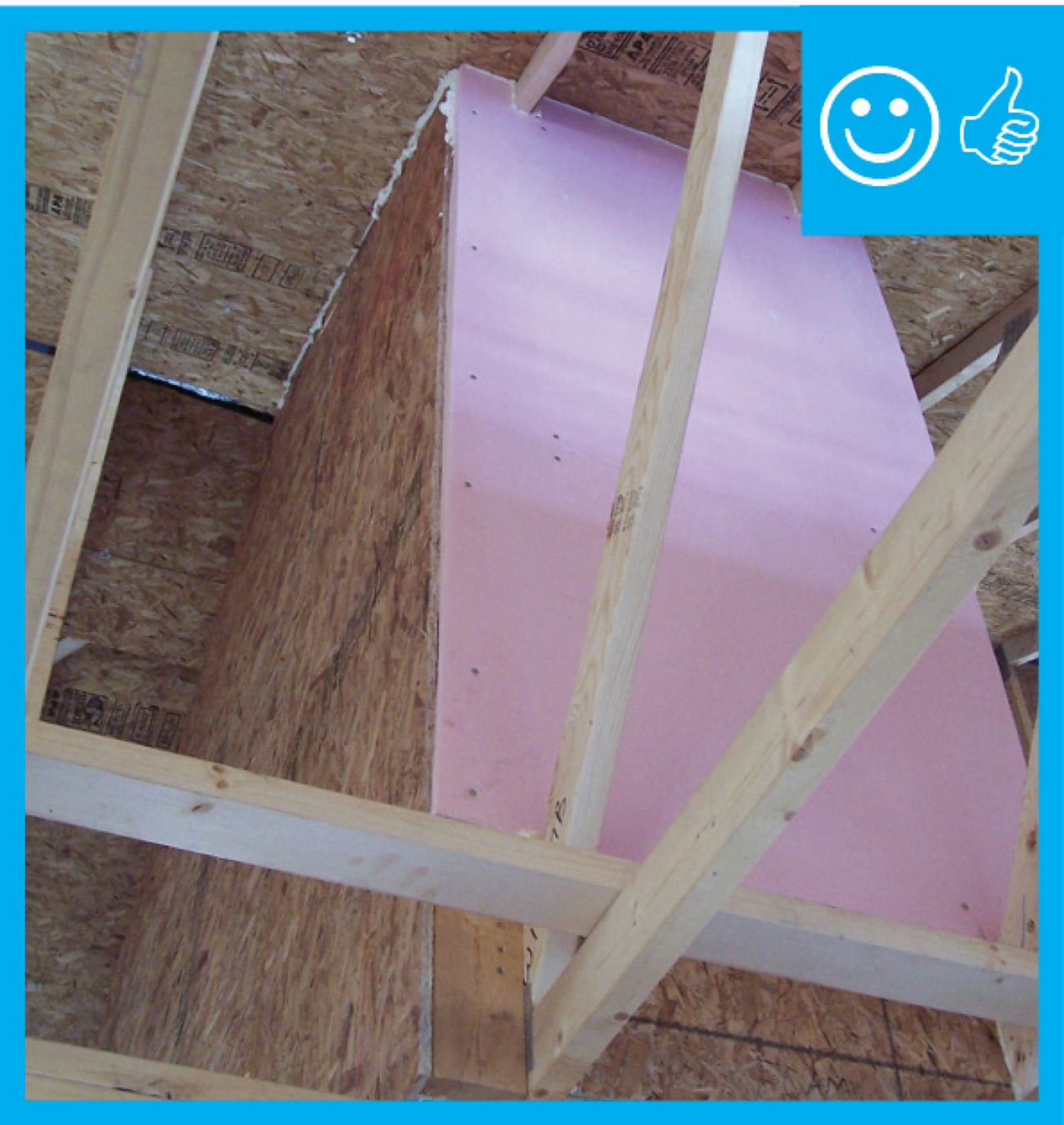
- Fill the stud cavities with spray foam, batt insulation, or rigid foam. Next, cover them with a layer of rigid foam to achieve the R-value level required for your climate zone.
Or,
Nail rigid foam in place over the studs and fill the
cavities with blown cellulose or blown fiberglass insulation.
- Caulk the drywall and rigid foam to the framing at all edges. Seal any seams in the rigid foam with caulk, tape or foam.
- Paint the drywall with latex paint to serve as the vapor barrier.

Figure 1. Frame, insulate, and air seal the walls of the
skylight shaft as you would an exterior wall.

Figure 2. Non-rigid cavity insulation should be covered with a rigid air barrier that is sealed at the edges.
How to Insulate a Solar Tube
- Install the tube according to the manufacturer’s instructions.
- Insulate the solar tube with plastic-covered flex duct insulation, or wrap the tube with unfaced fiberglass batt insulation. Secure the insulation in place with ties. Cover the unfaced batt insulation with flexible foil-faced insulation, and secure it with ties and metal tape.
- Use spray foam or caulk to air seal the solar tube to the ceiling from above.
- Caulk under the decorative ring on the room side of the ceiling.
Fully Aligned Air Barriers
- If non-rigid insulation is used, install a rigid air barrier to prevent the insulation from sagging and to create a continuous thermal barrier.
- Seal all seams, gaps and holes of the air barrier with caulk or foam.
- Install the insulation without any misalignments, compressions, gaps or voids so that it acts as both the air barrier and thermal boundary. Examples include foamboard, spray foam, or dense-pack insulation.
U.S. ENERGY STAR
ENERGY STAR (a voluntary program of the U.S. Environmental Protection Agency) highly recommends using a rigid air barrier, but
it is not a requirement.
An air barrier is defined as any durable, solid material that
blocks air flow between conditioned space and unconditioned space, including
necessary sealing to block excessive air flow at the edges and seams, and adequate
support to resist positive and negative pressures without displacement or
damage. ENERGY STAR recommends (but does not require) rigid air barriers.
Open-cell or closed-cell foam shall have a finished thickness >= 5.5 inches
or 1.5 inches, respectively, to qualify as an air barrier unless the
manufacturer indicates otherwise. If flexible air barriers, such as housewrap, are used, they shall be fully sealed at all seams and edges, and supported using
fasteners with caps or heads >= 1 inch in diameter, unless otherwise
indicated by the manufacturer. Flexible air barriers shall not be made of kraft
paper, paper-based products, or other materials that are easily torn. If
polyethylene is used, its thickness shall be >= 6 mil.
ENERGY STAR highly recommends (but does not require) inclusion of an interior air barrier at the band joists in Climate Zone 4 through 8.
All insulated vertical surfaces are considered walls (e.g.,
above- and below-grade exterior walls and knee walls) and must meet the air barrier
requirements for walls, with the exception of adiabatic walls in multi-family
dwellings. All insulated ceiling surfaces, regardless of slope (e.g., cathedral
ceilings, tray ceilings, conditioned attic roof decks, flat ceilings, sloped
ceilings), must meet the requirements for ceilings.
Ensuring Success
An infrared camera can be used to detect heat loss around
the skylight, if a sufficient temperature difference exists between the attic
and the conditioned space of the house. The insulation installed should be visually inspected by the site
supervisor.
Climate
Thermal Enclosure Checklist, Fully-Aligned Air Barriers. A complete air barrier shall be provided that is fully aligned with the insulation at the exterior surface of walls in all climate zones, and also at interior surface walls for Climate Zones 4-8.
Exhibit 2: DOE Zero Energy-Ready Home Target Home. Infiltration (ACH50): Zones 1-2: 3; Zones 3-4: 2; Zones 5-7: 2; Zone 8: 1.5. Envelope leakage shall be determined by an approved verifier using a RESNET-approved testing protocol.

Training
Images Showing Right and Wrong Methods

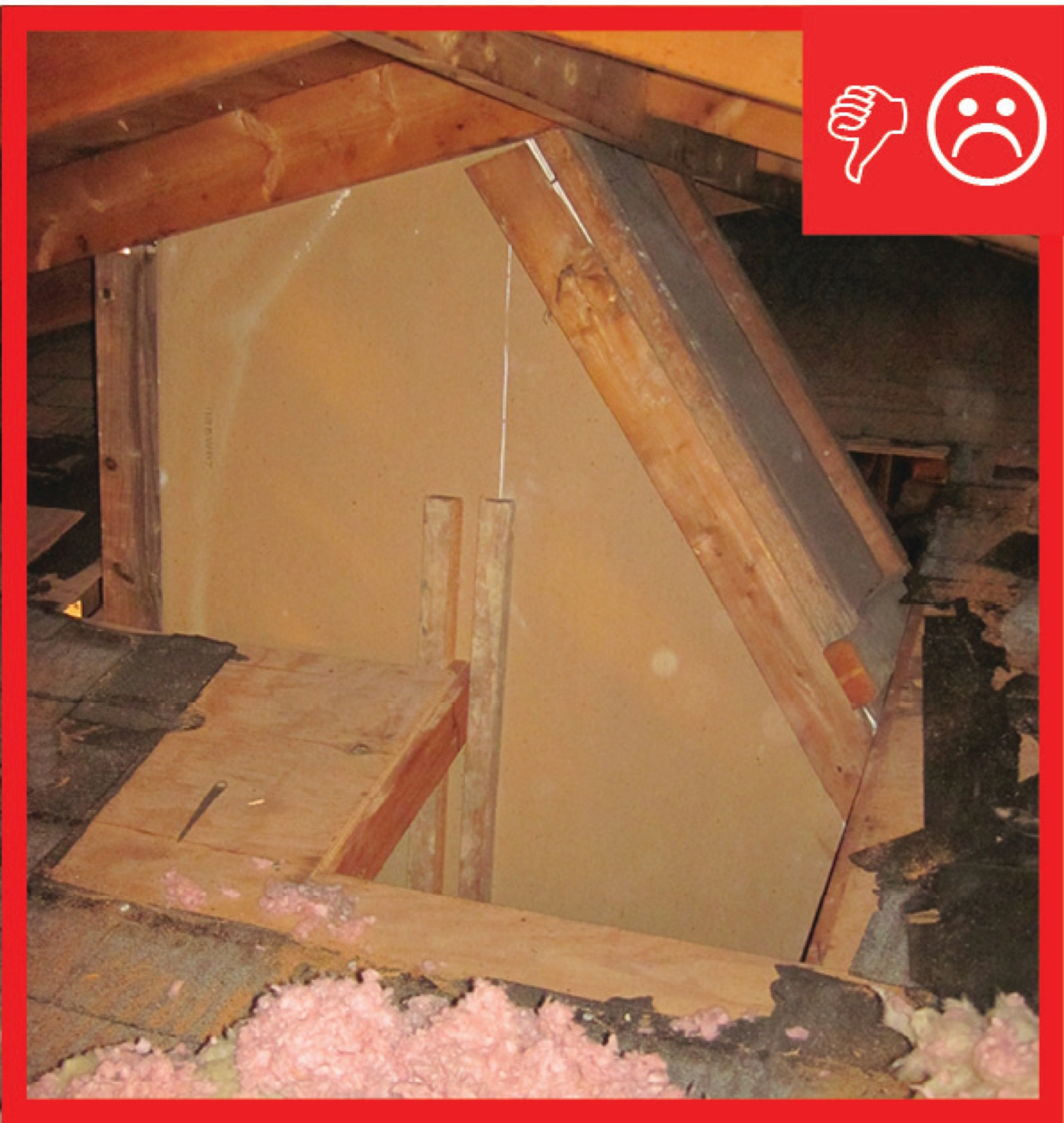
Wrong: Missing insulation at the skylight shaft walls and a modified truss component
(Photo courtesy of Kevin M. Leonard of The Ohio Home Inspections Company)
Reference: Thermal Enclosure System Rater Checklist
Guidebook
Author: U.S. EPA
This guide describes the details that serve as a visual reference
for each of the line items in the Thermal Enclosure System Rater Checklist.
Reference: Thermal Enclosure System Rater Checklist
Guidebook
Author: U.S. EPA
This guide describes the details that serve as a visual reference
for each of the line items in the Thermal Enclosure System Rater Checklist.
Reference: Thermal Enclosure System Rater Checklist
Guidebook
Author: U.S. EPA
This guide describes the details that serve as a visual reference
for each of the line items in the Thermal Enclosure System Rater Checklist.

Reference: Thermal Enclosure System Rater Checklist
Guidebook
Author: U.S. EPA
This guide describes the details that serve as a visual reference
for each of the line items in the Thermal Enclosure System Rater Checklist.

Reference: Thermal Enclosure System Rater Checklist
Guidebook
Author: U.S. EPA
This guide describes the details that serve as a visual reference
for each of the line items in the Thermal Enclosure System Rater Checklist.

Interesting: No shaft installed at the skylight that is open to the unfinished attic.
(Photo courtesy of Mike Bitterman of SNS home Inspections LLC)

Wrong: Missing cover of rigid material at the skylight shaft walls.
(Photo courtesy of Mike Bitterman of SNS home Inspections LLC)

Wrong: Missing insulation and missing cover of rigid material at the skylight shaft walls.
(Photo courtesy of Mike Bitterman of SNS home Inspections LLC)

Wrong: Missing insulation and missing cover of rigid material at the skylight shaft walls.
(Photo courtesy of Mike Bitterman of SNS home Inspections LLC)

Wrong: Missing insulation and missing cover of rigid material at the skylight shaft walls.
(Photo courtesy of Mike Bitterman of SNS home Inspections LLC)
Thermal Enclosure Checklist, Fully-Aligned Air Barriers. A complete air barrier shall be provided that is fully aligned with the insulation at the exterior surface of walls in all climate zones, and also at the interior surface of walls for Climate Zones 4-8. All insulated vertical surfaces are considered walls (e.g., above- and below-grade exterior walls and knee walls) and must meet the air barrier requirements for walls, with the exception of adiabatic walls in multi-family dwellings.
Exhibit 2: DOE Zero Energy-Ready Home Target Home. Certified under ENERGY STAR-Qualified Homes Version 3. Infiltration (ACH50): Zones 1-2: 3; Zones 3-4: 2.5; Zones 5-7: 2; Zone 8: 1.5. Envelope leakage shall be determined by an approved verifier using a RESNET-approved testing protocol.
ASTM E1677-11
Standard Specification for Air Barrier (AB) Material or System for Low-Rise Framed Building Walls. This specification covers minimum performances and specification criteria for an air barrier material or system for framed, opaque walls of low-rise buildings. The provisions are intended to allow the user to design the wall performance criteria and increase air barrier specifications for a particular climate location, function or design.
ABAA 07261
Self-Adhered Sheet Air Barrier. 2006. Air Barrier Association of America, Walpole, MA. This specification for self-adhered sheet air barriers is developed by a professional association--the Air Barrier Association of America--to provide guidance to the design professional.
ABAA 07262
Fluid-Applied Air and Vapor Barrier. 2012. Air Barrier Association of America, Walpole, MA. This specification for air barriers that are fluid-applied and also act as vapor barriers is developed by a professional association--the Air Barrier Association of America--to provide guidance to the design professional.
ABAA 07263
Closed Cell, Medium-Density Spray Polyurethane Foam Air Barrier. 2011. Air Barrier Association of America, Walpole, MA. This specification for closed cell, medium-density spray polyurethane foam air barriers is developed by a professional association--the Air Barrier Association of America--to provide guidance to the design professional.
ABAA 07265
Fluid-Applied Vapor Permeable Air Barrier. 2012. Air Barrier Association of America, Walpole, MA. This specification for fluid-applied, vapor-permeable air barriers is developed by a professional association--the Air Barrier Association of America--to provide guidance to the design professional.
2009 IECC
Section 402.4.1 Building thermal envelope: Joints (including rim joist junctions), attic access openings, penetrations, and all other such openings in the building envelope that are sources of air leakage are sealed with caulk, gasketed, weatherstripped, or otherwise sealed with an air barrier material, suitable film or solid material.* Table 402.4.2 Air Barrier and Insulation Inspection Component Criteria, Air Barrier and Thermal Barrier: Exterior wall insulation is installed in substantial contact and continuous alignment with the air barrier. Air-permeable insulation is not used as a sealing material.
2009 IRC
Section N1102.4.1 Building Thermal Envelope: Joints (including rim joist junctions), attic access openings, penetrations, and all other such openings in the building envelope that are sources of air leakage are sealed with caulk, gasketed, weatherstripped, or otherwise sealed with an air barrier material, suitable film, or solid material.* Table N1102.4.2 Air Barrier and Insulation Inspection Component Criteria, Air Barrier and Thermal Barrier: Exterior wall insulation is installed in substantial contact and continuous alignment with the air barrier. Air-permeable insulation is not used as a sealing material.
2012 IECC
Table R402.4.1.1 Air Barrier and Insulation Installation, Air Barrier and Thermal Barrier: A continuous air barrier is installed in the building envelope, including rim joists and exposed edges of insulation. Breaks or joints in the air barrier are sealed. Air-permeable insulation is not used as a sealing material.
2012 IRC
Table N1102.4.1.1 Air Barrier and Insulation Installation, Air Barrier and Thermal Barrier: A continuous air barrier is installed in the building envelope, including rim joists and exposed edges of insulation. Breaks or joints in the air barrier are sealed. Air-permeable insulation is not used as a sealing material.
