 Introduction
This article reviews some fundamental concepts of structural
design and presents them in a manner relevant to the design of light-frame
residential structures. The concepts form the basis for understanding the
design procedures, overall design approach, and how to inspect the structural
design of a residential dwelling. With this conceptual background, it is hoped
that the inspector will gain a greater appreciation for creative and efficient
design of homes, particularly the many assumptions that must be made.
What Is Structural Design?
The process of structural design is simple in concept but
complex in detail. It involves the analysis of a proposed structure to show
that its resistance or strength will meet or exceed a reasonable expectation.
This expectation is usually expressed by a specified load or demand and an
acceptable margin of safety that constitutes a performance goal for a
structure.
The performance goals of structural design are multifaceted.
Foremost, a structure must perform its intended function safely over its useful
life. The concept of useful life implies considerations of durability and
establishes the basis for considering the cumulative exposure to time-varying
risks (i.e., corrosive environments, occupant loads, snow loads, wind loads,
and seismic loads). Given, however, that performance is inextricably linked to
cost, owners, builders, and designers must consider economic limits to the
primary goals of safety and durability.
The appropriate balance between the two competing
considerations of performance and cost is a discipline that guides the art of
determining value in building design and construction. However, value is judged
by the "eye of the beholder," and what is an acceptable value to one person may
not be acceptable value to another (i.e., too costly versus not safe enough or
not important versus important). For this reason, political processes mediate
minimum goals for building design and structural performance, with minimum
value decisions embodied in building codes and engineering standards that are
adopted as law.
In view of the above discussion, a structural designer may
appear to have little control over the fundamental goals of structural design,
except to comply with or exceed the minimum limits established by law. While
this is generally true, a designer can still do much to optimize a design
through alternative means and methods that call for more efficient analysis
techniques, creative design detailing, and the use of innovative construction
materials and methods.
In summary, the goals of structural design are generally
defined by law and reflect the collective interpretation of general public
welfare by those involved in the development and local adoption of building
codes. The designer's role is to meet the goals of structural design as
efficiently as possible and to satisfy a client's objectives within the intent
of the building code. Designers must bring to bear the fullest extent of their
abilities, including creativity, knowledge, experience, judgment, ethics, and
communication aspects of design that are within the control of the individual
designer and integral to a comprehensive approach to design. Structural design
is much, much more than simply crunching numbers.
Load Conditions and Structural System Response
The concepts presented in this section provide an overview
of building loads and their effect on the structural response of typical
wood-framed homes. As shown in the table, building loads can be divided into
two types based on the orientation of the structural actions or forces that
they induce: vertical loads and horizontal (i.e., lateral) loads.
|
Building Loads Categorized by Orientation |
|
Vertical Loads |
Horizontal
(Lateral) Loads |
|
Dead (gravity)
Live (gravity)
Snow (gravity)
Wind (uplift on roof)
Seismic and wind (overturning)
Seismic (vertical ground motion) |
Wind
Seismic (horizontal ground motion)
Flood (static and dynamic hydraulic forces)
Soil (active lateral pressure) |
Vertical Loads
Gravity loads act in the same direction as gravity (downward or vertically) and include dead, live, and snow loads. They are
generally static in nature and usually considered a uniformly distributed or
concentrated load. Thus, determining a gravity load on a beam or column is a
relatively simple exercise that uses the concept of tributary areas to assign
loads to structural elements. The tributary area is the area of the building
construction that is supported by a structural element, including the dead load
(the weight of the construction) and any applied loads (the live load). For
example, the tributary gravity load on a floor joist would include the uniform
floor load (dead and live loads) applied to the area of floor supported by the
individual joist. The structural designer then selects a standard beam or
column model to analyze bearing connection forces (or reactions), internal
stresses (such as bending stresses, shear stresses, and axial stresses), and
stability of the structural member or system. The selection of an appropriate
analytic model is, however, no trivial matter, especially if the structural
system departs significantly from traditional engineering assumptions that are
based on rigid body and elastic behaviors. Such departures from traditional
assumptions are particularly relevant to the structural systems that comprise
many parts of a house, but to varying degrees.
Wind uplift forces are generated by negative (suction)
pressures acting in an outward direction from the surface of the roof in
response to the aerodynamics of wind flowing over and around the building. As
with gravity loads, the influence of wind uplift pressures on a structure or
assembly (such as the roof) are analyzed by using the concept of tributary areas and
uniformly distributed loads. The major difference is that wind pressures act
perpendicular to the building surface (not in the direction of gravity), and
that pressures vary according to the size of the tributary area and its
location on the building, particularly with proximity to changes in geometry (such as at the eaves, corners and ridges). Even though the wind loads are dynamic and highly
variable, the design approach is based on a maximum static load or pressure equivalent.
Vertical forces are also created by overturning reactions
due to wind and seismic lateral loads acting on the overall building and its
lateral force-resisting systems. Earthquakes also produce vertical ground
motions or accelerations that increase the effect of gravity loads. However,
vertical earthquake loads are usually considered to be implicitly addressed in
the gravity load analysis of a light-frame building.
Lateral Loads
The primary loads that produce lateral forces on buildings
are attributable to forces associated with wind, seismic ground motion, floods,
and soil. Wind and seismic lateral loads apply to the entire building. Lateral
forces from wind are generated by positive wind pressures on the windward face
of the building and by negative pressures on the leeward face of the building,
creating a combined push-and-pull effect. Seismic lateral forces are generated
by a structure's dynamic inertial response to cyclic ground movement. The
magnitude of the seismic shear or lateral load depends on the magnitude of
the ground motion, the building's mass, and the dynamic structural response characteristics
(such as dampening, ductility, natural period of vibration, etc.). For houses and
other similar low-rise structures, a simplified seismic load analysis employs
equivalent static forces based on fundamental Newtonian mechanics (F=ma) with
somewhat subjective or experience-based adjustments to account for
inelastic, ductile response characteristics of various building systems. Flood
loads are generally minimized by elevating the structure on a properly designed
foundation or avoided by not building in a flood plain. Lateral loads from
moving flood waters and static hydraulic pressure are substantial. Soil lateral
loads apply specifically to foundation wall design, mainly as an "out-of-plane" bending load on the wall.
Lateral loads also produce an overturning moment that must
be offset by the dead load and connections of the building. Therefore,
overturning forces on connections designed to restrain components from rotating
or to keep the building from overturning must be considered. Since wind is capable of
generating simultaneous roof uplift and lateral loads, the uplift component of
the wind load exacerbates the overturning tension forces due to the lateral
component of the wind load. Conversely, the dead load may be sufficient to
offset the overturning and uplift forces, as is often the case in lower design
wind conditions and in many seismic design conditions.
Structural Systems
As far back as 1948, it was determined that conventions in
general use for wood, steel and concrete structures are not very helpful for
designing houses because few are applicable, according to the National Bureau of Standards
(NBS). More specifically, the NBS document encourages the use of more
advanced methods of structural analysis for homes. Unfortunately, the study in
question and all subsequent studies addressing the topic of system performance
in housing have not led to the development or application of any significant
improvement in the codified design practice as applied to housing systems. This
lack of application is partly due to the conservative nature of the engineering
process, and partly due to the difficulty of translating the results of
narrowly-focused structural systems studies to general design applications. But
this document is narrowly scoped to address residential construction design.
If a structural member is part of a system, as is typically
the case in light-frame residential construction, its response is altered by
the strength and stiffness characteristics of the system as a whole. In
general, system performance includes two basic concepts known as load-sharing
and composite action. Load-sharing is found in repetitive member systems (including wood framing) and reflects the ability of the load on one member to be shared
by another, or, in the case of a uniform load, the ability of some of the load
on a weaker member to be carried by adjacent members. Composite action is found
in assemblies of components that, when connected to one another, form a "composite member" with greater capacity and stiffness than the sum of the
component parts. However, the amount of composite action in a system depends on
the manner in which the various system elements are connected. The aim is to
achieve a higher effective section modulus component than members taken separately.
For example, when floor sheathing is nailed and glued to floor joists, the
floor system realizes a greater degree of composite action than a floor with
sheathing that is merely nailed; the adhesive between components helps prevent
shear slippage, particularly if a rigid adhesive is used. Slippage due to shear
stresses transferred between the component parts necessitates consideration of
partial composite action, which depends on the stiffness of an assembly's connections. Therefore,
consideration of the floor as a system of fully composite T-beams may lead to
an non-conservative solution, whereas the typical approach of only considering
the floor joist member without composite system effect will lead to a
conservative design.
The information presented here addresses the strength-enhancing effect of load-sharing and partial composite action when information is available for
practical design guidance. Establishment of repetitive-member increase factors
(also called system factors) for general design use is a difficult task because
the amount of system effect can vary substantially depending on system assembly
and materials. Therefore, system factors for general design use are necessarily
conservative to cover broad conditions. Those that more accurately depict
system effects also require a more exact description of and compliance with
specific assembly details and material specifications.
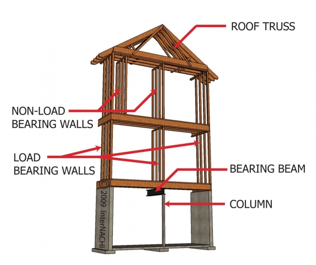
It should be recognized, however, that system effects do not
only affect the strength and stiffness of light-frame assemblies (including
walls, floors, and roofs). They also alter the classical understanding of how
loads are transferred among the various assemblies of a complex structural
system, including a complete wood-framed home. For example, floor joists are
sometimes doubled under non-load-bearing partition walls because of the
added dead load and resulting stresses determined in accordance with
accepted engineering practice. Such practice is based on a conservative
assumption regarding the load path and the structural response. In other words, the
partition wall does create an additional load, but the partition wall is
relatively rigid and actually acts as a deep beam, particularly when the top
and bottom are attached to the ceiling and floor framing, respectively. As the
floor is loaded and deflects, the interior wall helps resist the load. Of
course, the magnitude of effect depends on the wall configuration, including the amount
of openings and other factors.
This example of composite action due to the interaction
of separate structural systems or sub-assemblies points to the improved
structural response of the floor system such that it is able to carry more dead
and live loads than if the partition wall were absent. One whole-house assembly
test performed in 1965 demonstrated this effect. Hence, a double joist should
not be required under a typical non-load-bearing partition; in fact, a single
joist may not even be required directly below the partition, assuming that the
floor sheathing is adequately specified to support the partition between the
joists. While this condition cannot yet be duplicated in a standard analytic
form conducive to simple engineering analysis, the designer should be aware of
the concept when making design assumptions regarding light-frame residential
construction.
At this point, the inspector should consider that the response
of a structural system, and not just its individual elements, determines the manner
in which a structure distributes and resists horizontal and vertical loads. For
wood-framed systems, the departure from calculations based on classical
engineering mechanics (such as single members with standard tributary areas and
assumed elastic behavior) and simplistic assumptions regarding load path can be
substantial.
Load Path
Loads produce stresses on various systems, members, and
connections as load-induced forces are transferred down through the structure
to the ground. The path through which loads are transferred is known as the
load path. A continuous load path is capable of resisting and transferring the
loads that are realized throughout the structure from the point of load
origination down to the foundation.
As noted, the load path in a conventional home may be
extremely complex because of the structural configuration and system effects
that can result in substantial load-sharing, partial composite action, and a
redistribution of forces that depart from traditional engineering concepts. In
fact, such complexity is an advantage that often goes overlooked in typical
engineering analyses.
Furthermore, because interior non-load-bearing partitions are
usually ignored in a structural analysis, the actual load distribution is
likely to be markedly different from that assumed in an elementary structural
analysis. However, a strict accounting of structural effects would require
analytic methods that are not yet available for general use. Even if it were
possible to capture the full structural effects, future alterations to the
building interior could effectively change the system upon which the design was
based. Thus, there are practical and technical limits to the consideration of
system effects and their relationships to the load path in homes.
The Vertical Load Path
Figures 1 and Figure 2 below illustrate vertically-oriented loads
created, respectively, by gravity and wind uplift. It should be noted that the
wind uplift load originates on the roof from suction forces that act
perpendicular to the exterior surface of the roof, as well as from internal
pressure acting perpendicular to the interior surface of the roof-ceiling
assembly in an outward direction. In addition, overturning forces resulting
from lateral wind or seismic forces create vertical uplift loads (not shown in
Figure 2). In fact, a separate analysis of the lateral load path usually
addresses overturning forces, necessitating separate overturning connections
for buildings located in high-hazard wind or seismic areas. It may be feasible
to combine these vertical forces and design a simple load path to accommodate
wind uplift and overturning forces simultaneously.
Figure 1. Illustration of the
Vertical Load Path for Gravity Loads
Figure 2. Illustration of the
Vertical Load Path for Wind Uplift
In a typical two-story home, the load path for gravity loads
and wind uplift involves the following structural elements:
- roof sheathing;
- roof sheathing attachment;
- roof framing member (rafter or truss);
- roof-to-wall connection;
- second-story wall components (top plate, studs,
sole plate, headers, wall sheathing, and their interconnections);
- second-story-wall-to-second-floor connection;
- second-floor-to-first-story-wall connection;
- first-story wall components (same as second
story);
- first-story-wall-to-first-floor or foundation
connection;
- first-floor-to-foundation connection; and
- foundation construction.
From this list, it is obvious that there are numerous
members, assemblies, and connections to consider in tracking the gravity and
wind uplift load paths in a typical wood-framed home. The load path itself is
complex, even for elements such as headers that are generally considered simple
beams. Usually, the header is part of a structural system (see Figure 1), rather than an individual element single-handedly resisting the entire load originating
from above. Thus, a framing system around a wall opening, and not just a header,
comprises a load path.
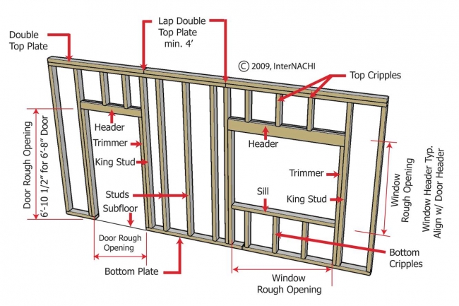
Figure 3. Illustration of Wall and Window Framing Components
Figure 1 also demonstrates the need for appropriately
considering the combination of loads as the load moves "down" the load path.
Elements that experience loads from multiple sources (e.g., the roof and one or
more floors) can be significantly over-designed if design loads are not
proportioned or reduced to account for the improbability that all loads will
occur at the same time. Of course, the dead load is always present, but the
live loads are transient. Even when one floor load is at its lifetime maximum,
it is likely that the others will be at only a fraction of their design load.
Current design load standards generally allow for multiple transient load
reductions. However, with multiple transient load reduction factors intended
for general use, they may not effectively address conditions relevant to a
specific type of construction, such as residential.
Consider the soil-bearing reaction at the bottom of the
footing in Figure 1. As implied by the illustration, the soil-bearing force is
equivalent to the sum of all tributary loads, dead and live. However, it is
important to understand the combined load in the context of design loads. Floor
design live loads are based on a lifetime maximum estimate for a single floor
in a single level of a building. But in the case of homes, the upper and lower
stories or occupancy conditions typically differ. When one load is at its
maximum, the other is likely to be at a fraction of its maximum. Yet, designers
are not able to consider the live loads of the two floors as separate transient
loads because specific guidance is not currently available. In concept, the
combined live load should therefore be reduced by an appropriate factor, or one
of the loads should be set at a point-in-time value that is a fraction of its
design live load. For residential construction, the floor design live load is
either 30 psf (for bedroom areas) or 40 psf (for other areas), although some
codes require a design floor live load of 40 psf for all areas. In contrast,
average sustained live loads during typical use conditions are about 6 psf
(with one standard deviation of 3 psf), which is about 15% to 20% of the
design live load, according to Chalk and Corotis (1980). If actual loading conditions are
not rationally considered in a design, the result may be excessive footing
widths, header sizes, and so forth.
When tracking the wind uplift load path (Figure 2), the
designer must consider the offsetting effect of the dead load as it increases
down the load path. However, it should be noted that building codes and design
standards do not permit the consideration of any part of the sustained live
load in offsetting wind uplift, even though it is highly probable that some
minimum point-in-time value of floor live load is present if the building is in
use, such as when it is furnished and/or occupied. In addition, other non-engineered load
paths, such as provided by interior walls and partitions, are not typically
considered. While these are prudent limits, they help explain why certain
structures may not "calculate" but otherwise perform adequately.
Depending on the code, it is also common to consider only
two-thirds of the dead load when analyzing a structure's net wind uplift
forces. The two-thirds provision is a way of preventing the potential error of
requiring insufficient connections where a zero uplift value is calculated in
accordance with a nominal design wind load (as opposed to the ultimate wind
event that is implied by the use of a safety margin for material strength in
unison with a nominal design wind speed). Furthermore, code developers have
expressed a concern that engineers might over-estimate actual dead loads.
For complicated house configurations, a load of any type may
vary considerably at different points in the structure, necessitating a
decision of whether to design for the worst case or to accommodate the
variations. Often, the worst-case condition is applied to the entire structure
even when only a limited part of the structure is affected. For example, a
floor joist or header may be sized for the worst-case span and used throughout
the structure. The worst-case decision is justified only when the benefit of a
more intensive design effort is not offset by a significant cost reduction. It
is also important to be mindful of the greater construction complexity that
usually results from a more detailed analysis of various design conditions.
Simplification and cost reduction are both important design objectives, but
they may often be mutually exclusive. However, the consideration of system
effects in design, as discussed earlier, may result in both simplification and
cost efficiencies that improve the quality of the finished product.
One helpful attribute of traditional platform-framed home
construction is that the floor and roof gravity loads are typically transferred
through bearing points, not connections. Thus, connections may contribute
little to the structural performance of homes with respect to vertical loads
associated with gravity (dead, live, and snow loads). While outdoor deck
collapses have occurred on occasion, the failure in most instances is
associated with an inadequate or deteriorated connection to the house, and not a
bearing connection.
By contrast, metal plate-connected roof and floor trusses
rely on connections to resist gravity loads, but these engineered components
are designed and produced in accordance with a proven standard and are
generally highly reliable. Indeed, the metal plate-connected wood
truss was first conceived in Florida in the 1950s to respond to the need for improved
roof structural performance, particularly with respect to connections in roof
construction.
In high-wind climates where the design wind uplift load
approaches the offsetting dead load, the consideration of connection design in
wood-framed assemblies becomes critical for roofs, walls, and floors. In fact,
the importance of connections in conventionally built homes is evidenced by the
common loss of weakly attached roof sheathing or roofs in extreme wind events, such as moderate-to large-magnitude hurricanes.
Newer prescriptive code provisions have addressed many of
the historic structural wind damage problems by specifying more stringent
general requirements (SBCCI; AF&PA). In many cases, the newer high-wind
prescriptive construction requirements may be improved by more efficient
site-specific design solutions that consider wind exposure, system effects, and
other analytic improvements. The same can be said for prescriptive seismic
provisions found in the latest building codes for conventional residential
construction (ICC; ICBO).
Lateral Load Path
The overall system that provides lateral resistance and
stability to a building is known as the lateral force-resisting system (LFRS).
In light-frame construction, the LFRS includes shear walls and horizontal
diaphragms. Shear walls are walls that are typically braced or clad with
structural sheathing panels to resist racking forces. Horizontal diaphragms are
floor and roof assemblies that are also usually clad with structural sheathing
panels. Though more complicated and difficult to visualize, the lateral forces
imposed on a building from wind or seismic action also follow a load path that
distributes and transfers shear and overturning forces from lateral loads.
The
lateral loads of primary interest are those resulting from:
- the horizontal component of wind pressures on
the building's exterior surface area; and
- the inertial response of a building's mass and
structural system to seismic ground motions.
As seen in Figure 3, the lateral load path in wood-framed
construction involves entire structural assemblies (including walls, floors, and
roofs) and their interconnections, not just individual elements or frames, as
would be the case with typical steel or concrete buildings that use discrete
braced framing systems. The distribution of loads in Figure 3's
three-dimensional load path depends on the relative stiffness of the various
components, connections, and assemblies that comprise the LFRS. To complicate
the problem further, stiffness is difficult to determine due to the
non-linearity of the load-displacement characteristics of wood-framed assemblies
and their interconnections. Figure 4 below illustrates a deformed light-frame
building under lateral load; the deformations are exaggerated for conceptual
purposes.
Figure 4. Illustration of the
Lateral Load Path
Figure 4. Illustration of
Building Deformation under Lateral Load
Lateral forces from wind and seismic loads also create
overturning forces that cause a "tipping" or "roll-over" effect. When these
forces are resisted, a building is prevented from overturning in the direction
of the lateral load. On a smaller scale than the whole building, overturning
forces are realized at the shear walls of the LFRS such that the shear walls
must be restrained from rotating or rocking on their base by proper connection.
On an even smaller scale, the forces are realized in the individual shear wall
segments between openings in the walls. As shown in Figure 3, the overturning
forces are not necessarily distributed as might be predicted. The magnitude and
distribution of the overturning force can depart significantly from a typical
engineering analysis depending on the building or wall configuration.
The overturning force diagrams in Figure 3 are based on
conventionally built homes constructed without hold-down devices positioned to
restrain shear wall segments independently. It should be noted that the effect
of dead loads that may offset the overturning force and of wind uplift loads
that may increase the overturning force is not necessarily depicted in Figure 3's
conceptual plots of overturning forces at the base of the walls. If rigid-steel
hold-down devices are used in designing the LFRS, the wall begins to behave in
a manner similar to a rigid body at the level of individual shear wall
segments, particularly when the wall is broken into discrete segments as a
result of the configuration of openings in a wall line.
Summary
In summary, significant judgment and uncertainty attend the
design process for determining building loads and resistance, including
definition of the load path and the selection of suitable analytic methods.
Designers are often compelled to comply with somewhat arbitrary design
provisions or engineering conventions, even when such conventions are
questionable or incomplete for particular applications such as a wood-framed
home. At the same time, individual
designers are not always equipped with sufficient technical information or
experience to depart from traditional design conventions. Therefore, this information serves as a resource for both inspectors and designers who are
considering the installation and use of improved analytic methods when current
analytic approaches may be lacking.