Visual Inspection of Concrete
by Nick Gromicko CMI®, Ben Gromicko, and Kenton Shepard
Most information available about concrete is written for contractors, for those who design concrete mixes, and for those who perform invasive testing. The information provided here is specifically for those who perform non-invasive, visual inspections of concrete, such as home inspectors or commercial property inspectors using the International Standards of Practice for Inspecting Commercial Properties.
In evaluating concrete problems, one of the important decisions home inspectors must make is determining whether a problem is the result of conditions that have stabilized with a low chance of continuing future problems, or whether the conditions that caused the problem are such that there is a high probability that problems will continue or worsen.
 Chemically, concrete is a complicated material, and a visual inspection will not always answer those questions. Basic knowledge of concrete mixes, installation, weathering, and the other factors that can affect how it ages, in addition to the illustrations and photo examples provided here, will give inspectors the best chance of making sound decisions and recommendations to their clients.
Constituent Material Properties
- Cement + water = cement paste
- Cement paste + sand = mortar
- Mortar + aggregate = concrete
Binders
Although Portland cement is the most commonly used binder, pozzolans may be substituted. Pozzolans are materials that, in addition to undergoing primary hydration, undergo a secondary hydration, producing a gel that fills tiny voids between cement particles, making concrete less porous and less likely to absorb moisture or chemical solutions that can damage concrete or steel reinforcement.
Aggregates
Because aggregates are quarried locally, their texture, weight, strength, and absorptive and reactive properties vary, and this variation can affect the concrete’s properties.
Water
The chemical composition of water can affect concrete, but more important is the ratio of water-to-cement paste used in the mix. Cement needs only about 25% water for hydration to take place. To improve its workability, the ratio is commonly increased to around 45%. Increasing the ratio of water makes concrete more porous; as this extra water rises to the surface as bleed water and through evaporative drying, it leaves behind capillary voids. These capillary voids weaken concrete and make it more absorbent, increasing the chances of freeze damage and attack from liquid chemicals. It is not uncommon for the water-to-cement ratio to be well over 45%. If concrete starts to harden before it’s placed, water is sometimes added at the job site to maintain workability.
Mix Design
The constituent materials which are included in the mix, their proportions, the order in which they are combined, the length of time and method by which they are mixed, and the length of time between mixing to placing all affect the quality of concrete. With each decision and operation, there is a chance that mistakes will be made.
Environmental Conditions
The environmental conditions that exist during placing, finishing and curing concrete will have an effect on how it develops. The ground and air temperatures, wind speed, cloud cover, and the absorbent qualities of the substrate will affect newly placed concrete.
Workmanship
The quality of workmanship can have an effect. Here are some common mistakes:
- inadequate cover of reinforcement steel. Inadequate cover can lower steel’s resistance to corrosion. This is a very common problem;
- incomplete consolidation. Concrete is usually consolidated with a mechanical vibrator. Concrete being placed in forms should be placed in layers, with each layer being vibrated when it is placed. Placing too much concrete at any one area at a time, or failing to vibrate concrete adequately can result in incomplete consolidation, causing a honeycomb pattern;
Honeycombing due to poor consolidation
- creating cold joints. Cold joints are created when concrete is poured against concrete that has already hardened to some degree. This condition results in a weakened bond between the existing and the newly poured concrete;
A cold joint in concrete
- finishing the surface too soon. Troweling while the bleed water is still on the surface forces water back into the surface layer of the concrete. This increases the water-to-cement ratio and results in a concrete surface that is overly porous and of substandard durability; and
- improper curing methods or lack of curing. Improper curing can encourage cracking and reduce strength development.
Cracks
The advantage to inspectors in being able to accurately determine the source of cracking is in understanding whether the condition that caused the cracking has stabilized so that it is no longer likely to cause additional cracking or encourage the propagation of existing cracks. Many cracks, like those caused by concrete shrinkage, are shallow cracks caused by forces that allow conditions to stabilize relatively quickly and do not lead to structural problems. Others, like those caused by soil subsidence or changes in soil volume, are caused by forces that can continue to affect concrete for a long time. This long-term instability can continue to cause serious structural problems over the long term.
The cause of cracking can be related to:
- the properties of the constituent materials;
- the design mix;
- the surrounding environment in which concrete is installed;
- mixing, placement, finishing and curing practices;
- the type of use; and
- maintenance practices.
Commonly Observed Shrinkage Cracks in Poured Concrete Foundations
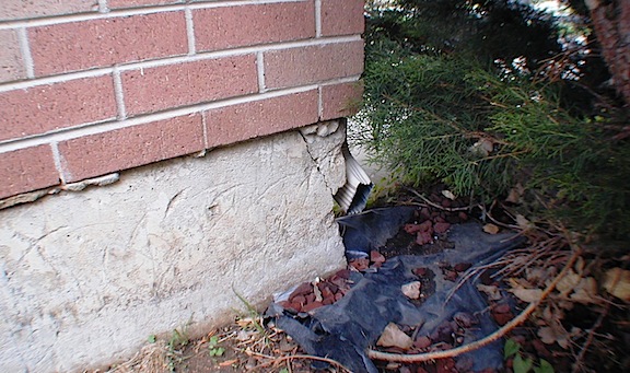
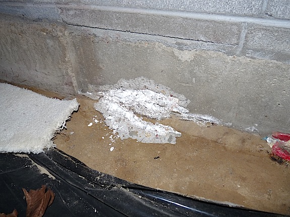
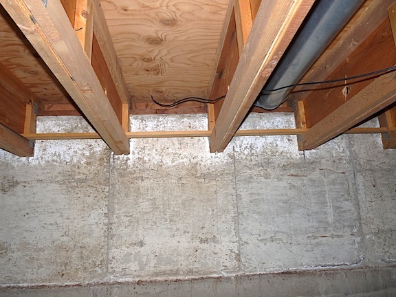
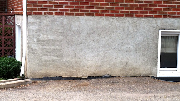
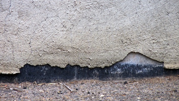
Here are some inspection images taking during a home inspection of a house with a poured concrete foundation.


There's an indication of water intrusion or penetration through the foundation at the bottom corner of the foundation wall. Efflorescence is observed there.


The cracks observed appear to be shrinkage cracks. They are not major structural concerns. They do require monitoring. There's no major movement or displacement of the concrete, meaning that the foundation surfaces around the cracks are in the same plane.


The cracks are hairline. They are slightly more open at the top of the foundation wall than they are at the bottom. Near the bottom, the cracks seem to be more closed and tight.


When there are observed indications of water intrusion or penetration through the foundation wall, the inspector should recommend further evaluation by a qualified contractor and correction of the water problem, which may include an epoxy injection into the crack.
Crack Basics
CLASSIFICATION OF CRACKS
Type of Cracking | Form of Crack | Primary Cause | Time of Appearance |
Plastic settlement | Above and aligned with steel reinforcement | Subsidence around rebar; excessive water in the mix. | 10 minutes to |
Plastic shrinkage | Diagonal or random | Excessive early evaporation | 30 minutes to six hours |
Thermal expansion and contraction | Transverse (example: across the pavement) | Excessive heat generation or temperature gradients | One day to two or three weeks |
Drying shrinkage | Transverse or pattern | Excessive water in the mix; poor joint placement; joints over-spaced | Weeks to months |
Freezing and thawing | Parallel to the concrete surface | Inadequate air entrainment; non-durable coarse aggregate | After one or more winters |
Corrosion of reinforcement | Above reinforcement | Inadequate concrete cover; ingress of moisture or chloride | More than two years |
Alkali-aggregate reaction | Pattern cracks; cracks parallel to joints or edges | Reactive aggregate plus moisture | Typically, over five years, but may be much sooner with highly reactive aggregate |
Sulfate attack | Pattern cracks | External or internal sulfates promoting the formation of ettringite | One to five years |

1. Formwork Movement
Relatively small movements of formwork in the early stages of hardening will cause cracks.
2. Sub-Grade Movement
Movement of the sub-grade, such as settling or heaving, can crack concrete. This may be caused by changes in soil volume in response to changes in the soil’s moisture content, or it may be caused by subsidence. Subsidence is settling that can have a number of causes. Sub-surface mining, extraction of natural gas, the dissolution of limestone or conditions related to groundwater can all cause soil to settle. An example is when groundwater dissolves the carbonate cement holding sandstone particles together, and then carries away the particles, creating a void in the soil.
This map shows areas in the U.S. where subsidence can be a problem.
3. Plastic Shrinkage
Plastic shrinkage is caused by excessively high rates of evaporation from the surface of the concrete before it has hardened. For hydration to take place, a ratio of only about 25% water-to-cement is needed. To improve workability, water is often added to around 45%. This surplus water forces cement particles apart, suspending them in water. Once the concrete has been placed, the heavier aggregate particles settle, and the weight of the mix forces excess water to the surface. This excess water is called bleed water. Once the bleed water has evaporated from the surface, the concrete will still be wet and the surplus water will continue to dry upward through evaporation from the surface, and downward through absorption by the sub-grade, unless the concrete is installed directly on a vapor barrier, such as plastic, in which case, all drying will be upward.
Drying does not take place at an even rate throughout the concrete matrix. It happens most rapidly at the upper surface through evaporation and more slowly at the bottom through absorption. The rate at which the sub-grade absorbs water will depend on its absorbent properties, including its porosity, moisture content, and even its electro-chemical properties.
Resistance to Shrinkage

Resistance to shrinkage
The illustration above shows the underlying layer of concrete (B) that is slower to dry and offers resistance to shrinkage. In the image on the left, a vapor barrier is installed directly beneath the concrete so that all drying must take place from the upper surface. On the right, the lack of a vapor barrier allows drying both to the air and to the sub-grade, reducing the capillary force along AB, which reduces the resistance to shrinkage and makes concrete at the surface less likely to crack.
4. Plastic Settlement
Plastic settlement can be caused by subsidence around rebar. This is sometimes related to excessive water in the mix.
As soon as concrete is placed, it begins to consolidate, and as bleed water rises to the surface, cement particles consolidate and the concrete settles. The settling process is restrained by reinforcement steel and, under certain circumstances, cracks will develop directly above the steel. This condition is best recognized by the crack pattern, which typically reflects the even spacing of the reinforcement steel.

Plastic settlement cracking

Repeating pattern of cracks where rebar cross-members connect longitudinal rebar
Plastic settlement cracks can be caused by:
- inadequate concrete cover of the steel;
- excessive water in the concrete;
- form movement or blowout; or
- poor consolidation practices.
5. Autogenous Shrinkage
Plastic shrinkage is shrinkage caused by the loss of water to the atmosphere. Autogenous shrinkage is shrinkage that takes place with no loss of water to the atmosphere. Autogenous shrinkage is caused by internal drying, with water being absorbed by the constituent materials in the concrete. As the long-term chemical hydration process continues – and it can continue for many years -- water in the pores within the cement paste is absorbed, and the pores are filled, to some degree, by materials produced during hydration. This process leads to decreased permeability and increased strength and durability of the cement paste. Absorption of water from the pores also causes shrinkage.
Since there is no loss of water to one exposed surface, autogenous shrinkage is more uniform than plastic shrinkage. However, tensile stresses still develop, and embedded steel can cause anomalies in an area of concrete with relatively uniform stress. These anomalies can cause variations in stress within the concrete that are relieved by cracking. Autogenous shrinkage cracking will be shallow and is not a structural issue. The cracks may look similar to those formed during plastic shrinkage and are often propagations of cracks created during plastic shrinkage.
Outside corners are also high-stress points.
6. Premature Freezing
Concrete is porous; it can absorb water. When absorbed water freezes, it expands, and if no method is used to accommodate the expansion, it can lead to cracking, or flakes of concrete may break loose and separate from the surface. This is especially true if absorbed moisture freezes before the concrete has aged enough to gain significant strength. Concrete should be kept warm until it has had a chance to harden adequately. The appearance of concrete damaged by premature freezing will vary with environmental conditions, but it often appears as widespread spalling or delamination of the surface layer, since cracking is often parallel to the surface.
7. Scaling and Crazing
Scaling
Scaling is the shedding of flakes of hardened concrete at the surface. It can be caused by a number of conditions:
- Exposure to freezing and thawing can cause scaling, which can be made worse by the application of de-icing salts.
- Concrete that has been improperly cured or that has inadequate air entrainment will be less resistant to scaling caused by freezing.
- Finishing operations started while bleed water is still on the surface can weaken the surface layer and cause dusting or scaling. When concrete is placed during hot and dry conditions, the bleed water may appear to be gone, but the surface may still be actively bleeding. The bleed water may be evaporating as it reaches the surface. During such conditions, finishing operations may be started under the mistaken impression that the surface is done bleeding.
- Over-working the surface during finishing will reduce the air content of the surface concrete, leaving it weaker and more vulnerable to scaling due to freezing conditions.
- Fertilizers, such as ammonium sulfate and ammonium nitrate, will chemically attack the concrete surface.
- Poor drainage causes water to pool, and water containing de-icing salts can also lead to pooling on the surface for extended periods of time. This can happen where snowplows pile snow on sidewalks and driveways.

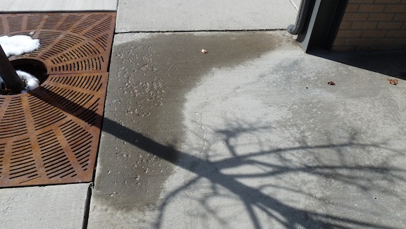
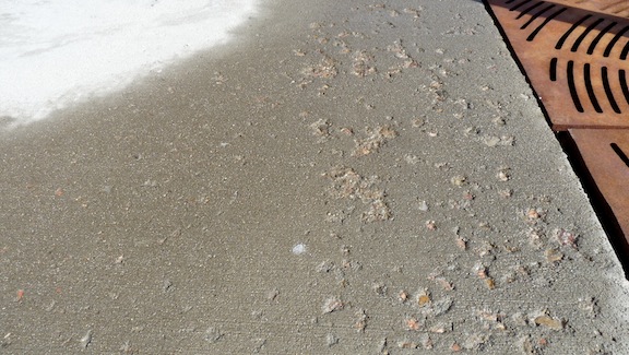
Small patches of flaking

Smaller patches of damage have expanded to form a large area of damage.
In addition to properly timing finishing operations, proper curing will help prevent dusting and scaling. In hot and dry environments, the sub-grade should be dampened before the concrete is placed, and the surface should be kept damp to keep it from drying too quickly. In cool and damp environments, a water-repelling sealer should be applied to keep the surface from absorbing too much water. Concrete is most fragile during the first year after placing, so de-icing chemicals should be avoided during that time, and the concrete should be protected from absorbing moisture just before freezing weather develops.
During inspections, the most common places to find this type of damage are driveways and garage floors. Even if ice-melt is not used on walkways by a home’s occupant, the undercarriage of vehicles can accumulate frozen slush from roadways that contains chloride solutions. This slush will melt from cars parked in driveways and garages and be absorbed into the concrete. Poor finishing practices, such as over-working the concrete or working bleed water back into the surface, will leave the surface weak and more likely to flake. Concrete less than a year old that may be exposed to chlorides should have a sealer applied that is designed specifically for concrete to help prevent freeze damage. Sealers may have to be re-applied periodically, depending on the type of chemicals used on the roadways in a given area, as well as the climate zone. It is sometimes possible to remove a weak or damaged surface layer of concrete and apply a thin, bonded re-surfacing product based on Portland cement, latex-modified concrete or polymer-modified mortar. Inspectors can recommend that their clients investigate products or methods that have been used successfully in the area where the home is located.
Flaking at a crawlspace footing
In the photo above, the flake has detached from the surface of the footing, which was caused by the expansion of a pocket of minerals in the concrete. Negative grade around the home caused the soil to become saturated. Moisture eventually diffused through the porous concrete, eventually reaching the expansive minerals. The clue that this was caused by moisture is the white mineral salts, called efflorescence.
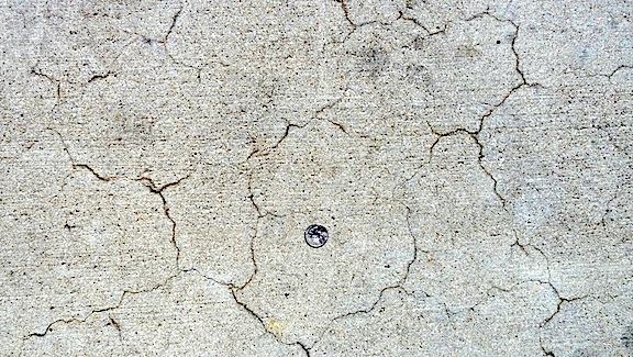
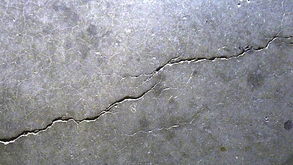
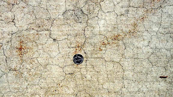
Crazing
Pattern cracking, also called map cracking and craze cracking, appears as a network of random cracking on the concrete’s surface. The cracking is usually shallow (less than 1/8-inch deep) and not a structural issue. It’s seldom a durability problem but more of a cosmetic one.
The area enclosed by pattern cracking may be anywhere from 1/2-inch to 4 inches across.

Pattern cracking can be caused by the following:
- poor curing practices. Environmental conditions such as low humidity, high outside temperatures, direct sunlight, and wind can create high rates of evaporation from the surface layer of concrete. Resistance to shrinkage from the underlying concrete causes stress that is relieved by craze cracking;
- excessive water in the mix;
- over-vibration of the concrete, causing coarse aggregate to settle and cement paste to concentrate at the surface;
- over-working the surface with a steel trowel during finishing;
- performing finishing operations while bleed water is still on the surface; and
- sprinkling cement dust on the surface to soak up bleed water.
8. Drying Shrinkage
Drying shrinkage is shrinkage that takes place after the concrete has hardened and some degree of bonding has developed between the cement paste and the aggregate. As concrete continues to dry, it will continue to shrink. Drying shrinkage includes both shrinkage that takes place while losing moisture to the air and autogenous shrinking, as noted previously. The cracks will look similar to those formed during plastic shrinkage. Cracking during drying shrinkage may be the propagation of cracks that initially developed during plastic shrinkage.
Transverse Cracking
Drying shrinkage cracks typically extend across the face of a wall or across pavement, which is called transverse cracking.
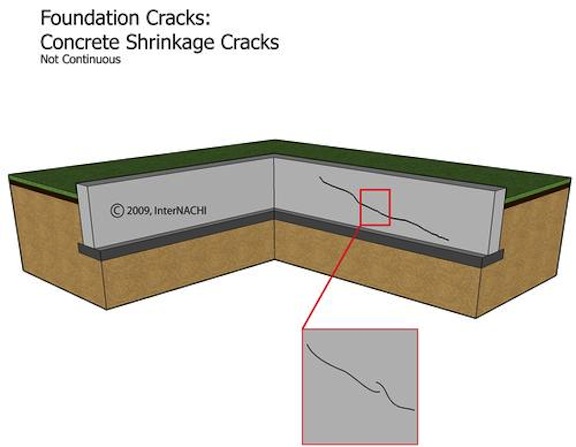
Wall shrinkage cracks are often diagonal and do not extend to the corners.
They are typically shallow and linear, although such cracks are not always continuous.
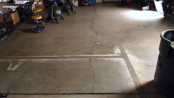
Notice the lack of control joints in this shrinkage crack.
A typical interruption in a shrinkage crack
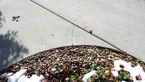
Transverse shrinkage cracks appear where the tensile strength of concrete is lowest, such as where concrete is thinner at a control joint, or across an area of concrete with cracks on either side. Shrinkage cracks propagate from the tips, so concrete adjacent to the termination of a shrinkage crack is under more tensile stress than concrete in other parts of a slab.
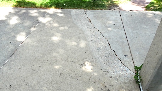
![]()
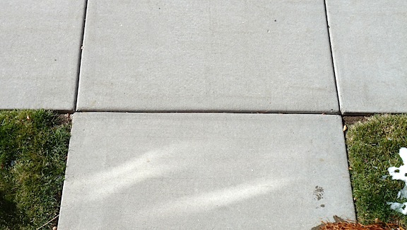
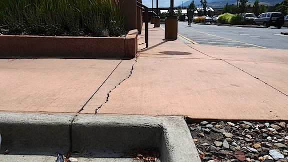
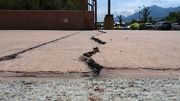
A transverse shrinkage crack in pavement extends between cracks located in control joints.
In the photo above, areas A and B were the points at which the highest stress developed due to adjacent cracking in the control joints, so that is where the walkway panel split first, following the path of greatest stress. As the slab continued to shrink, the two cracks connected with each other to form a single transverse crack.
Re-Entrant Corners
Another type of configuration where stresses are concentrated is where concrete forms a re-entrant corner.

A re-entrant corner crack
A re-entrant corner with properly placed control joints
This close-up of the corner shows cracking taking place in the control joints, as it should.
Re-entrant corners are high-stress areas prone to transverse cracking from plastic shrinkage. A re-entrant corner is where any inside corner forms an angle of less than 180 degrees into the body of the slab. As the concrete dries and shrinks, the wedge shape of the re-entrant corner encourages concrete to crack off the point of the angle into the slab.
Re-entrant cracking at the apex of a radiused re-entrant corner
The photo above shows concrete cracking off the apex of a radiused re-entrant corner, even though there is a control joint located nearby.

Red areas show approximate locations of stress concentrations
This image shows how steep stress gradients can be, or how concentrated stresses can be according to shape. If the stress gradient were shallower, the stress at the apex would be less concentrated and would have been relieved by cracking at the control joint.
9. Thermal Cracking
Variations in the temperature of concrete cause it to expand and contract. Significant differences in temperature between the outer and inner portions can cause concrete to crack. Especially when concrete is fairly new and has not gained much strength and is in an expanded condition from the heat generated during hydration, as it cools, cracks can develop. Cracking can be stimulated by temperature gradients that may be the result of differences in thickness, such as when the exterior cools faster than the interior, although this is more typical in massive structures. It may be caused by environmental conditions, such as cold weather. The forces at work are similar to resistance to shrinkage.
10. Creep
Although we may think of concrete as being brittle, it will actually bend instead of breaking under certain conditions. Concrete creep is the deformation of a concrete structure under sustained load. Long-term pressure or stress on concrete can make it change shape. This deformation typically happens in the direction in which the force is applied. Inspectors are most likely to see creep in retaining walls, or in foundation walls that are not reinforced by a floor structure. Creep does not necessarily cause concrete to fail. The photos below show creep and cracking caused by long-term pressure from tree roots.

Creep
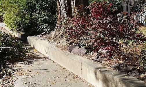
Creep with cracking
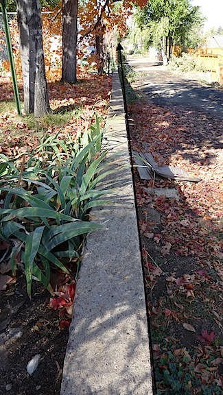
Creep
Concrete in high-humidity environments, such as damp basements and crawlspaces, will experience accelerated rates of deformation compared to similar concrete in low-humidity conditions.
11. Design Load and Overload
Cracking can be the result of a design that is inadequate for a particular type of load. Cracking may be caused by the failure of a foundation to resist the weight of water-saturated soil, as in the illustrations below.

Lateral pressure resulting in a horizontal crack

Lateral pressure resulting in a vertical crack
The photos below show a garage built into a hillside. Cracking along the back wall of the garage is the result of the concrete’s inability to resist lateral forces from the soil. The force may have been created by machinery during the original backfill operations, or it may have resulted over time from the weight of water-saturated soil. The correction was to raise a section of the end wall to help resist rotation, and to install a steel beam as a strongback. Inspectors should not recommend specific corrections but should recommend that a structural engineer be consulted to design corrective measures.

The problem was located in the garage to the right.

A section of the concrete foundation wall at the left was extended (the black rectangle).

A steel I-beam acts as a strongback. (The top flange of the beam is facing the camera).
Foundation Repair
The illustration below shows a method for stabilizing a foundation against a lateral load using helical tiebacks. The tiebacks are screwed hydraulically into solid soil, and then the extensions are added.

Helical tiebacks are used to stabilize a basement foundation wall.
12. Design and Sub-Grade
Concrete foundations must be designed in such a way that they resist forces created by problems with the sub-grade, including settling and heaving.
Settling Soils
There are two types of settling: compaction and consolidation.
Compaction is the displacement of air-filled voids between soil particles. Inadequately compacted soil will settle as the weight of the structure presses the particles together. This process continues until the force required to further compact the soil exceeds the force placed upon the soil by the structural load – in other words, until the state of compaction reaches equilibrium with the load, and the condition becomes stable. The time required to reach stabilization varies with soil type and its characteristics.
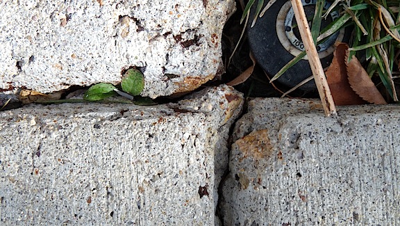
Settling caused by inadequate compaction
Vertical displacement occurred as the lower end of the walkway settled.
The crack shown in the photos above was caused by inadequate compaction. If shrinkage were the cause, the crack would have appeared in the control joint. Another clue is the vertical displacement that appeared as the lower end of the walkway settled.
Hillside lots are sometimes created by cutting into the hillside and using the soil that’s removed from the uphill side as fill on the low side. Poor compaction can cause cracking of the foundation and the interior and exterior wall coverings.

Settling caused by inadequate compaction during cut and fill
Poor soil consolidation is another cause of settling. Consolidation is the displacement of water-filled voids between soil particles. Settling from consolidation may take longer to reach equilibrium than settling caused by compaction, since water has greater resistance to moving through soil than air.
Settling may be uniform, or it may occur at different rates at different parts of a foundation. Although sandy and coarse-grain soils settle faster than fine-grain soils such as clay, the soil beneath a home often varies in composition. Settling rates can vary not only with the type and characteristics of the soil, but also with the loads carried by and the configuration of the foundation footings. The illustration below shows how poor compaction or consolidation, or soil with poor load-bearing capacity, can cause settling that damages foundations.

Soil with poor load-bearing capacity allows settling.
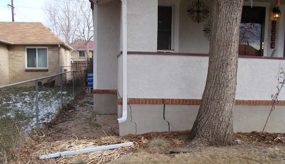
An example of differential settling
In the photo above, a column transferred the roof load to the soil, which settled under the weight. Portions of the wall that bear no roof load settled less. Note that the cracking is slightly wider at the top.
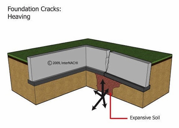
Heaving Soils
Heaving may be caused by clay-based soils that expand in volume when they absorb water. These soils, called expansive soils, can damage foundations and concrete floor slabs through uplift. Soils capable of damaging foundations may contain as little as 5% of the active mineral, and may exert as much as 5,500 pounds per square foot (psf) of pressure against the concrete. Special methods must be used when building foundations on expansive soil in order to avoid future damage as the soil expands. One method is to rest the foundation on piers that extend down below the zone of water-content fluctuation, where the soil is stable, or to bedrock.

Drilled pier foundation
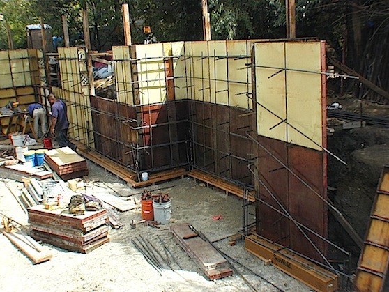
This drilled-pier foundation will be placed on void forms and piers that are resting on bedrock.
In the photo above, holes extending down to the bedrock at the corners and mid-spans of the walls will be filled with reinforced concrete to form piers. The top 3 feet of rebar are visibly protruding from the holes. Cardboard void forms placed on the ground between the piers and inside the forms are strong enough to bear the weight of the concrete when it is poured, creating voids beneath the walls. If the soil heaves, the void forms will be crushed. The amount of heaving will have to be greater than the thickness of the void forms (typically, 6 inches) for the soil to come into contact with the bottom of the foundation walls. Inspectors may be able to verify that a drilled-pier foundation has been installed but they will not be able to confirm the depth to which the piers were drilled, so they should observe carefully for signs of foundation movement.
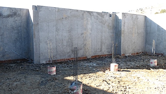
Void forms after the walls have been poured
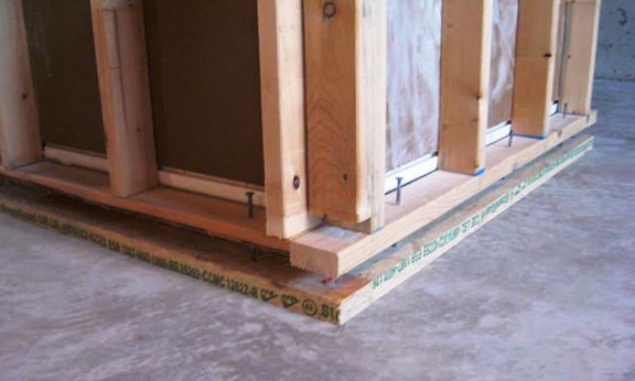
The doubled bottom plate accommodates heaving.
Another method used to accommodate heaving is the use of doubled bottom plates. When inspecting a home in an area known to have expansive soil, inspectors should identify basement walls framed without this method as defective. In a newer home inspectors should recommend that correction be made. If walls have been in place for a significant period of time with no damage occurring, this condition will probably not be a problem unless something happens that introduces water to the soil beneath the basement floor. This might be a leak from plumbing pipes, valves or fixtures, or leaking of laundry equipment. Inspectors should state this in their reports.
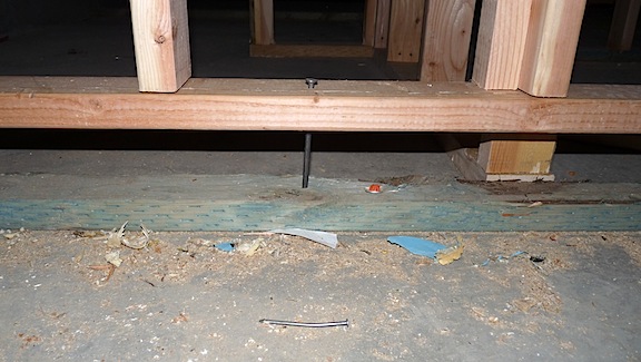
A doubled bottom plate connected to a wall with a single bottom plate
| PINK | Over 50% of these areas are underlain by soils with abundant clays with a high potential for swelling. |
| BLUE | Less than 50% of these areas are underlain by soils with clays with a high potential for swelling. |
| ORANGE | Over 50% of these areas are underlain by soils with abundant clays having a slight to moderate potential for swelling. |
| GREEN | Less than 50% of these areas are underlain by soils with abundant clays with a slight to moderate potential for swelling. |
| BROWN | These areas are underlain by soils with little to no clay with potential for swelling. |
| TAN | Data is insufficient to determine the clay content or the potential for soil swelling. |
This map shows regions with expansive soil.

This cracking was caused by expansive soil.
With soil expansion severe enough to cause cracking, heaving should be apparent. As shown in the photo above, it was possible to feel the high spot at the crack by walking across the floor.
Crack caused by heaving
Cracks caused by heaving may be wider at the top, as shown in the illustration above, but this condition can also be caused by settling toward one corner.
Vertical displacement creates trip hazards and you may see concrete ground down to alleviate this problem, as in the photo above. Inspectors who observe these types of trip hazards should recommend correction. In areas with expansive soils, inspectors need to be diligent in identifying negative and neutral grade around the foundation and recommending mitigation. Typical mitigation involves correcting the grade and/or installing a plastic membrane beneath the topsoil around the home’s perimeter to act as a barrier to runoff seeping down next to the foundation.
A swimming pool located close to a home’s foundation can saturate the soil. Water diffusing through the air-blown mortar (gunite) wall of a swimming pool introduces moisture into the soil. In most cases, the pool’s walls are not designed to resist the swelling forces created by expanding soil. If the pool is installed near the home’s foundation, the resulting pressure can damage the pool’s structure and the home’s structure.
Freezing Soils
Soils may also heave when water-saturated soil freezes.
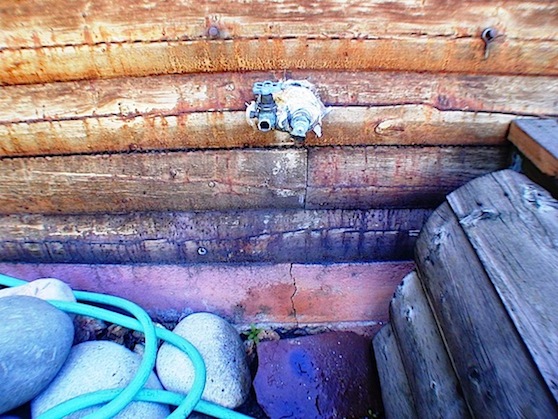
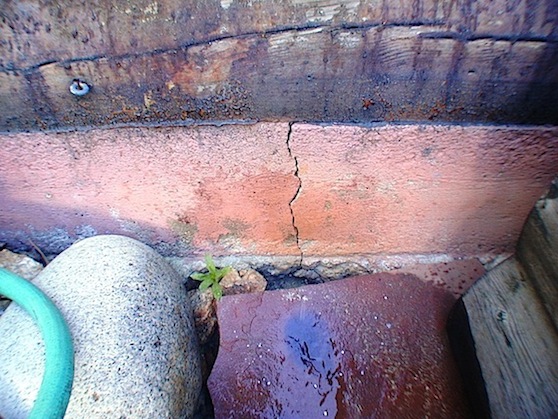
The photos above show a foundation crack that was caused by soil that was saturated by a leaking hose bib. When the water in the soil froze, it expanded, cracking the foundation. Notice that the crack is wider at the top.
Tree Damage
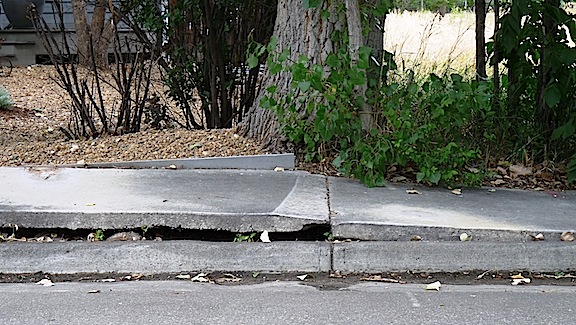
Tree roots may also cause concrete to heave. As shown in the photo below, it was less expensive to grind off the protruding portion than to demolish and replace the walkway.
Soil Shrinkage
Expansive soil expands when it absorbs water, but it also shrinks as it loses water. This process can leave voids that can reduce the soil’s ability to support a structural load. When foundations are supported by piers that depend on friction to support their structural loads, shrinking soil can cause a loss of friction, reducing the foundation’s ability to support the structure and allowing foundation settlement.
13. Fatigue
Concrete fatigue is long-term failure due to repeated loading (cycles). Loads may be applied in tension, compression, torsion (twisting), bending, or a combination of these actions. In fatigue, each individual load is less than a single static or unchanging load that would exceed the strength of the concrete. Fatigue has to do with the development and propagation or growth of cracks and micro-cracks, and the failure of the bond between the cement paste and aggregate. Crack development and bond failure worsen slowly over time and are influenced by a number of variables. Fatigue is not something most inspectors will be able to identify and is less common in residential construction than in commercial and especially industrial structures. An in-depth discussion of fatigue requires engineering expertise, and recognizing or diagnosing it lies beyond InterNACHI’s Standards of Practice.
14. AAR, ASR and DEF
AAR
Ideally, aggregates used in concrete would be chemically inert. But because aggregates are quarried locally, there is sometimes little choice in the types of aggregate that are available for use in concrete. Some types of aggregate react chemically with alkali hydroxides in cement to produce a gel. When this gel is exposed to moisture, it expands, and this expansion can crack concrete. There are two types of alkali-aggregate reactions (AAR): alkali-silica reaction (ASR), and alkali-carbonate reaction (ACR).
ASR
ASR is of more concern because aggregates containing reactive silica materials are more common. Inspectors will not be able to conclusively identify damage from ASR visually. It can be identified through petrographic analysis, which is examination by a petrographer using a special microscope. Petrography is the branch of geology that concerns the study of rocks.
Exudation is a liquid or viscous, gel-like material discharged through a pore, crack or opening in the surface of concrete. The presence of exudation is a strong indication that cracking has been caused by ASR.
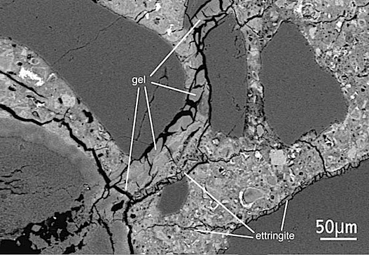
This photo, taken through a microscope, shows gel formation between fine aggregate particles.
If water should reach this gel through pores or cracks, it will expand, cracking the concrete.
This condition may be caused by ASR, but only laboratory testing can confirm this.
Inspectors do not need to identify the source of the condition – only its severity.
The recommendation here would be to consult with a concrete contractor
to gain an understanding of options and cost for replacement.
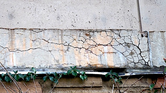
The two photos below show concrete of approximately the same age containing aggregate that reacts differently to moisture. Cracking and discoloration along the control joint, shown in the lower photo, is more severe and the concrete will deteriorate more quickly than that shown in the upper photo .

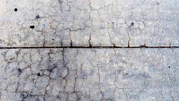
Although this cracking looks similar to pattern cracking, the fact that it graduates in intensity,
starting at the control joint, indicates that absorption from moisture accumulating in the control joint is the cause. Pattern cracking would be fairly uniform across the surface.
DEF
Delayed ettringite formation (DEF) is a condition that describes a chemical reaction caused by curing at excessively high temperatures, resulting in gaps and cracks that form around the aggregate, weakening the concrete. This is another condition that inspectors will not be able to identify visually.

This photo shows cracks emanating from the aggregate.
Under a load, especially a cyclic load, these cracks can grow, weakening the concrete.
15. Steel Corrosion
Corrosion of embedded steel is the most common cause of concrete problems. As steel corrodes, the corrosion product expands, and this expansion can crack concrete and cause sections to break loose in flakes. Steel is typically protected by a thin film that develops as part of a chemical reaction with cement. This coating, called passivity, lowers the rate of corrosion to a point at which it becomes insignificant. Several conditions can damage the passive coating and dramatically increase the rate at which reinforcement steel corrodes.
Loss of Alkalinity
In order for concrete to sustain passivity, it must maintain a level of alkalinity between 9.5 and 13. If the alkalinity drops below the required level, the rate at which embedded steel corrodes will increase significantly. The pH of concrete can be lowered by either of two processes:
1. carbonation, in which acidic gases, such as carbon dioxide (CO2), can be absorbed into the concrete; and
2. leaching by water.
Since most concrete is porous, CO2 will be slowly absorbed by the surface and find its way deeper into the concrete. Also, water will slowly diffuse through it. If steel has inadequate concrete cover, usually 1-1/2 inches minimum, the pH of the concrete encasing the steel may be lowered to the point at which the passive layer is damaged or destroyed and the rate of the steel’s corrosion may increase dramatically.
Another way in which CO2 or water may reach the concrete surrounding steel is through cracks caused by excessive structural loading, shrinkage, plastic settlement, or other reasons. Inadequate cover is especially common in the risers of concrete stairs, as shown in the photos below.

Corrosion typical of inadequate cover
Concrete cover will be thinner at control joints.

Repairs are common at control joints in stairs at well-maintained properties.
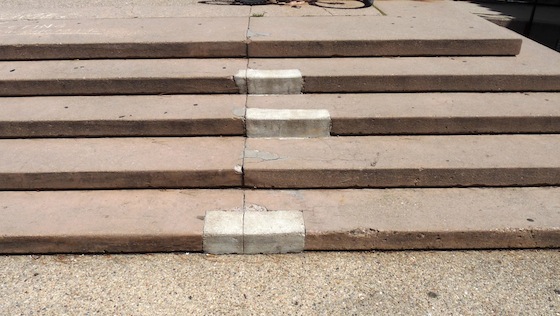
Poor-quality repairs may result in the re-appearance of corrosion.
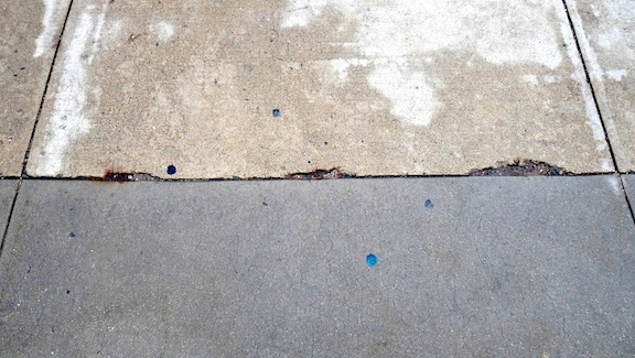
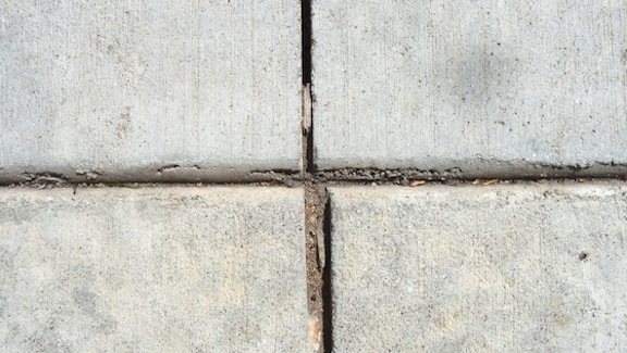
Inadequate cover due to control joints is also common in flatwork. Where control joints are installed perpendicular to embedded rebar, the areas at which the control joint crosses each bar may develop cracking and corrosion, and eventually spalling or flaking. This common condition is called D-cracking and is shown in the photo below.
Depassivation by Chlorides
Chloride solutions commonly used to keep pavements ice-free can destroy the passive layer that protects steel. They may reach it by liquid diffusion through porous concrete or through cracks.
Contamination by Atmospheric Pollution
Reinforcement steel may be contaminated by chlorides before it is embedded in concrete, during either transportation or storage. In addition to de-icing solutions, salt air in coastal environments can contaminate exposed steel.
Galvanic Corrosion
Galvanic corrosion occurs when two dissimilar metals are in contact with each other in the presence of moisture. This can happen when aluminum conduit or copper wire is in contact with steel.
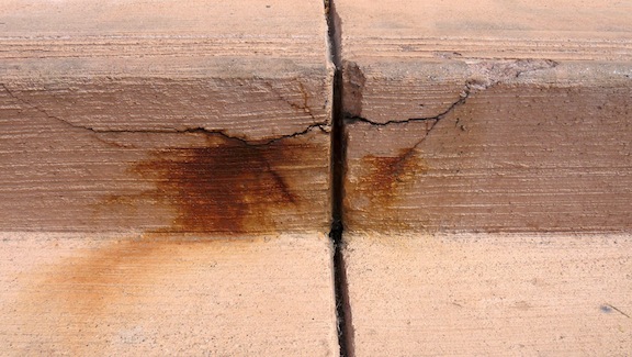
Plastic Settlement Cracking
Plastic settling can cause cracking above steel reinforcement that can allow corrosive agents, such as water and chloride solutions, to reach and corrode steel. Cracks resulting from plastic settlement do not always cause corrosion. If reinforcement steel has adequate coverage, corrosive agents will not reach it. A closer look (below) shows discoloration that has developed along the resulting settlement crack.

If discoloration above a settling crack were caused by corroding rebar, it would be rust-colored. The discoloration in the photo above is most likely caused by reactive aggregate. Discoloration will spread and cracking will worsen slowly.
16. Freeze-Thaw Cycling
Again, as moisture is absorbed by concrete, it may freeze and expand, creating damage that often appears as spalling or surface delamination. Air entrainment is used to solve this problem. Air entrainment creates tiny voids spaced closely together in the concrete. As water turns to ice, it expands into these voids, reducing internal pressure.
Inspectors should look for spalling damage from a lack of air entrainment at projects where the concrete was mixed on-site, or if the mix was designed by someone with an inadequate knowledge of concrete.
Sulfate Attack
There are two types of sulfate attack: internal and external. External attack is more common.
External Sulfate Attack
External sulfate attack occurs when water containing dissolved sulfates is absorbed into porous concrete. A chemical reaction takes place that can vary in severity and may appear as:
- extensive cracking;
- expansion;
- bond failure between the aggregate and the cement paste; and/or
- a chemical alteration of the cement paste’s composition.
Common sources of sulfate are:
- seawater;
- sulfide mineral oxidation in nearby clay deposits;
- sulfuric acid produced by bacterial action in sewers; and
- sulfates present in brick spread over the long term, especially if moisture is present.
Internal Sulfate Attack
Sulfates are sometimes introduced into the mix in aggregate by using an excessive amount of gypsum or through other contaminants. Inspectors will not be able to visually identify damage from sulfate attack.
Joints
Concrete typically has two types of joints installed: isolation joints and control joints.
Isolation Joints
Isolation joints, also called expansion joints, are used to separate two adjacent areas of concrete in order to allow them to expand and contract independently.
The new floor, which will expand, is contained by the foundation wall.
A common example is a new floor that is poured in a garage or basement after the footings and foundation walls are already in place. After the concrete is placed, the heat of hydration will cause the slab to expand. Without isolation joints, this expansion would crack the foundation wall.

Fibrous isolation-joint material allows the slab to expand without damaging the foundation wall.
When a fibrous material is installed around the perimeter before placing the concrete, as the concrete floor expands, the fiber will compress. As the concrete starts to cool and contract, this fibrous material will expand.
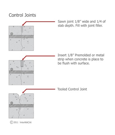
Control Joints
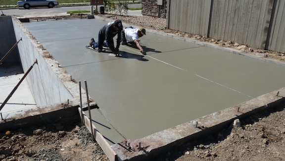
Control joints, also called contraction joints, are narrow slots that are either pressed into the concrete while it is still plastic or cut into the concrete using a saw after it has hardened.
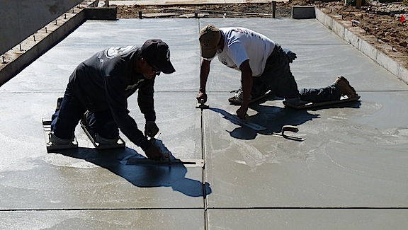
The workman on the right is finish-troweling a tooled control joint.
The vertical joint is a sawn joint and the horizontal joint is tooled.
The tooled joint is the most common type, followed by the sawn joint.
The purpose of control joints is to help control the location of shrinkage cracks. Control joints weaken concrete by making it thinner. Since concrete will crack where stresses are highest and the concrete is weakest, control joints should be installed at high-stress areas. Whether or not the joints are placed correctly depends on how well the person placing them understands where stresses are likely to develop.
The inspector’s main concerns with control joints are over-spaced joints, and especially a lack of joints. The spacing of control joints is the responsibility of the designer and can vary with:
- slab or wall design;
- slab or wall thickness;
- type, amount and location of steel reinforcement;
- shrinkage potential of the concrete;
- base friction;
- floor or wall slab restraints (embedded steel or block-outs for windows);
- environmental factors (temperature, wind, humidity, etc.); and
- the method and quality of curing.
The ideal shape for concrete partitioned off by control joints is square, or rectangular not to exceed 1.5x1.
In general, the spacing should not exceed 30 times the thickness, not to exceed 15 feet. Joint depth should be one-quarter the thickness of the slab but not less than 1 inch. Some types of concrete are designed to maximize the spaces between control joints, but inspectors will not be able to identify these mixes visually, and if shrinkage cracking and control joint spacing both seem excessive, the cracking is probably related to spacing.
Curing Concrete
Excessively hot concrete may develop thermal cracking if temperatures are not uniform throughout, since concrete will expand and contract at different rates according to temperature. Also, overly hot concrete will lose moisture quickly, which can cause excessive shrinking and cracking from resistance to shrinkage. In some cases, water necessary for hydration will evaporate. The following describe some curing methods.
- ponding or immersion: Once the surface has hardened, it is flooded. Water evaporates from the surface of the flooded area instead of from the surface of the concrete. This minimizes shrinkage and cracking.
- spraying or fogging: This is effective but water is lost to evaporation.
- moisture-retaining fabrics: These work well. Burlap is often used.
- impervious paper: This slows the rate of evaporation.
- plastic sheets: These slow the rate of evaporation.
Curing Compound
For home inspectors, the concern with concrete curing compounds is that they can interfere with the bond between concrete and stone or ceramic tile floor coverings when mortar-based adhesives are used. There are two basic types of curing compounds: permanent and temporary.
Permanent Curing Compounds
Permanent, moisture-impermeable curing compounds fill the pores in concrete, creating a smooth surface. Mortar forms a better mechanical bond to rougher surfaces. Complete removal of the permanent curing compound is the only way to ensure a successful installation when a Portland cement-based setting material is used. A permanent curing compound can be removed by mechanically scarifying the concrete’s surface to a depth below that which the curing compound has penetrated. Scarifying exposes the concrete’s pores. Mechanical scarification involves blasting the surface with materials such as shot, beads, high-pressure water, or abrasives.
Temporary Curing Compounds
Temporary curing compounds dissipate gradually, either through chemical reactions or by oxidation from exposure to the ultraviolet radiation in sunlight. This means that concrete treated with temporary curing compounds and dependent on UV exposure for dissipation must be left exposed to sunlight for an adequate amount of time.
Temporary curing compounds can also leave a residue that interferes with the bond between mortar and concrete. Mechanical abrasion can be used to get rid of this residue. Such mechanical abrasion methods include bush hammering, planers and grinders. Abrasion doesn’t penetrate the surface as deeply as scarification, so it may not be adequate. Depending on the curing product, scarification may also have to be used on temporary curing compounds. Acids used to remove curing compounds may interfere with the bond between mortar and concrete.
Curing/Sealing Compounds
Curing/sealing compounds are applied for the same purpose as curing compounds: to reduce excessive water loss from the surface. But curing/sealing compounds have UV inhibitors and are designed to remain in place to help prevent the compounds from yellowing. A curing/sealing compound might be used if the concrete floor is to be left exposed. Some of these types of compounds have UV inhibitors that are only good for the short term, and concrete protected by these will eventually start to turn yellow. If an inspector sees yellowing on a concrete surface exposed to sunlight but not on a less-exposed surface, the use of an inappropriate curing/sealing compound may be the cause of the problem.
Surface Sealers
Surface sealers are applied to cured concrete and are designed to provide a protective finish. There are a number of choices in surface sealers, depending on whether the floor will need to resist chemical attack or abrasion, and whether aesthetics are important. Sealers applied over stains will magnify the stains. When a sealer is being re-applied over an existing sealer, problems can arise from chemical incompatibility. There are two types: film-forming and penetrating.
Film-forming sealers are typically acrylic resins, and the surface must be clean and dry for proper application. For penetrating sealers, all potential contaminants must be removed first, including:
- curing compounds;
- form-release agents; and
- existing sealers.
Problems with Sealers
Solvent-Based Sealers
Inspectors may find a number of problems with solvent-based sealers, which often have a combination of sources:
- Bubbles in the sealer are an indication that it was applied when the concrete was too hot, causing the solvent to evaporate on contact and form bubbles.
- Peeling or flaking from the surface indicates poor adhesion that may be caused by:
- surface contaminants, such as dust or dirt; or
- too much water present on the surface of the concrete when the sealer was applied.
- A white or frosted appearance can be caused by:
- efflorescence on the surface of the concrete beneath the film;
- high evaporation rates during application, typically caused by excessively high air or concrete temperatures, or wind;
- moisture trapped between the concrete and sealer;
- adhesion failure between the concrete surface and the sealer, or between multiple coats of sealer.
- The formation of globs of sealer can be caused by excessively high air or concrete temperatures during sealer application.
- Sticky or tacky sealer may be caused by:
- grease, oil, solvents or other substances that attack the sealer;
- plasticizing agents in rubber-backed mats or weatherstripping (like that found on garage doors) can leach out, softening the sealer.
Water-Based Sealers
Problems with water-based sealers can have their own set of causes:
- If the sealer has turned milky-white:

Sealer applied over an excessively wet surface
- Surfactants in the sealer may have reacted with moisture on the concrete surface. Surfactants are compounds that lower the surface tension of the interface between the concrete and the sealer.
- Moisture may be trapped between the sealer and the concrete.
- The air or concrete temperature may have been too low when the sealer was applied.
- Water-based sealant can also curdle or form globs. This can be caused by:
- concrete surfaces that have not been adequately neutralized, rinsed and dried after being acid-stained or acid-washed; or
- concrete that was too hot when the sealer was applied.
Here are some examples of sealer failure:

Improper sealer application with a roller

Poor sub-base preparation
Reaction to residue, probably from a stamp-release agent

Improper sealer film formation
The Effect of Regulations
Federal and state regulations designed to lower the toxic environmental effects of various chemical products, including sealers, have influenced the manufacture and use of sealers, including the following:
- Some solvent-based sealers are no longer available.
- The concrete industry has shifted toward the increased use of water-based, low-VOC (volatile organic compound) products.
- The minimum temperature for application has been raised, shortening the application season in colder climate zones.
- In states with more restrictive regulations, such as California, concrete may need to be re-sealed more often than in the past due to decreased effectiveness of the allowed sealers.
While these sealers may have been environmentally toxic, this toxicity made them effective, so newer products made for the same purpose may not last as long.
Moisture-Related Problems
Efflorescence
Efflorescence is a common moisture-related problem. It appears as a white powder on the surface of hardened concrete. It is the result of water-soluble chemical salts being carried through porous concrete to the surface by moisture moved via diffusion, capillary action or osmosis. Upon reaching the surface, the water evaporates, leaving behind the chemical salts.
The forces at work are:
- diffusion: 0.3 to 0.5 psi;
- capillary action: 300 to 500 psi; and
- osmosis: 3,000 to 5,000 psi.
Diffusion, as it is defined in this context, is the movement of water from areas of high concentration, which is the water-saturated soil against the exterior of the foundation walls and footings, toward areas of low concentration, which are the dry interior surfaces of the walls and footings. This movement across an area of difference is called a gradient, and the moisture gradient described is relevant to other materials in structures, in addition to masonry.
Early in the process of developing efflorescence, moisture moves through the concrete by diffusion. The accumulation of salts on the surface of concrete attracts water, which, according to the laws of physics, is drawn toward high concentrations of salt in order to achieve equilibrium of the salt solution by dilution. As salt accumulations increase, so do the forces of attraction, with diffusion becoming capillary action, and finally increasing to osmosis. With repeated wetting and drying, salts are deposited not only on the surface, but in the concrete near the surface. When dry salt deposits near the surface reach a critical concentration, sudden wetting may cause them to expand, detaching a flake similar to the one in the photo below.

This condition is called spalling.
The two photos below show how efflorescence appears at the locations that experience the greatest amount of exposure to water. In the image below, severe efflorescence and undermining were caused by 40 years of downspout discharge to the foundation at this location. The large amounts of water channeled to the foundation were moved low in the wall and soil by gravity.

Severe efflorescence from downspout discharge
Notice the water stains on the wood beam. Wood beams resting in pockets in concrete foundation walls should have adequate room for air circulation to carry away moisture by evaporation, helping to keep moisture in the wood below levels that can lead to decay. Any time moisture levels in wood beams exceed about 20%, wood decay is taking place. Any time moisture levels exceed about 28%, mold colonies are probably growing. When the levels drop below these percentages, these harmful actions cease.
Efflorescence from neutral grade
In the photo above, efflorescence from neutral grade appears higher in the wall. There are two reasons for this. First, surface runoff from neutral grade was spread over a larger area, resulting in less intense exposure to water, compared to the foundation shown in the photo above it. Second, this home is located in an area with clay soil, down through which water moves relatively slowly.
Also, in the photo just above, efflorescence is visible on the wall along the top of the footing. This is because the footing and foundation wall were poured separately, creating a cold joint through which moisture moves more easily.
Rising Damp
Whenever concrete is placed directly on grade, a potential exists for capillary action to draw water out of the soil, up through the porous concrete and into the home’s structure. In many part of the English-speaking world, this is called rising damp. In more extreme cases, moisture may reach and damage drywall and wall plaster, a variety of floor covering materials and/or the adhesives that bond them to the floor.
Capillary Break
Using proper building methods that prevent this problem, a capillary break is installed on top of the sub-grade before the concrete is poured. The capillary break may be in the form of gravel or plastic sheeting. Gravel has voids large enough that capillary action cannot draw water through them, and it will also drain quickly. Plastic sheeting acts as a vapor barrier so that water in the form of vapor is prevented from being drawn into and wicking through the concrete. Sand or pea gravel should not be used, since the voids between their particles are small enough that capillary forces will prevent the sand or gravel from draining quickly.
Sand Beneath Concrete
In some places, construction practices include installing plastic sheeting on grade and then installing a layer of sand on top of the plastic before pouring the concrete. This is an especially bad practice and can cause moisture problems with floor coverings. The sand layer becomes saturated with water during the curing process, from landscape irrigation, from groundwater, or from rain. Drying forces will have to overcome capillary forces, and this can be an extremely slow process, sometimes measured in years. If plastic is installed beneath the sand, the situation will be worse, since the sand cannot dry downward and will have to dry upward, pulled by the concentration gradient. When this happens, anything in contact with the surface of the concrete will get wet.
If an inspector finds a failed bond between a floor covering and the concrete beneath it, s/he can use a moisture meter to check the moisture level. Even if the level is not elevated at the time of the inspection, high moisture levels and damage may have occurred in the first few years after original construction.
Correction of Rising Damp
The correction for rising damp is a difficult proposition in a finished home. The concrete must be coated with a product impermeable to water. This can be troublesome because of the high pH of concrete. Either the pH must be permanently lowered before the product is applied or the product must adhere to the material. The answer is to find an epoxy coating that will adhere to concrete with a high pH. They exist, but they may be expensive and/or hard to find. Acid neutralizers will leave a salt residue. Calcium silicates don’t react completely and will leave behind alkalis that are the problem in the first place. It is sometimes possible to install a ceramic tile floor over damp concrete. The grout lines will release moisture from the concrete to the atmosphere.
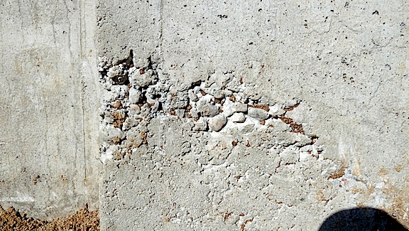
Aggregate Pop-Out
An aggregate pop-out is a cone-shaped surface depression that is caused by one of two reactions of aggregate to moisture exposure.
Freezing
High-absorptive, low-density aggregate expands and ruptures when it freezes. As it freezes, the aggregate expands, rupturing the overlying concrete. With this type of pop-out, the initial rupture is actually in the aggregate, and part of the aggregate separates and remains attached to the detached cone of concrete.
ASR
Pop-outs can also be the result of ASR. Aggregates may react with alkali in cement or other products to produce a gel. If that gel is close enough to the surface to encounter absorbed moisture, it can expand, causing a cone of overlying concrete to break loose.
The location of damage reflects the amount of moisture exposure.
The lack of ruptured aggregate indicates that this damage was most likely caused by reactive aggregate.
Slab Curling
Curling describes the distortion of a concrete slab when the edges of the slab curl up or down due to temperature or moisture differentials at the top and bottom surfaces. As the slab begins to harden, if the top or bottom surface changes size relative to the other (usually due to shrinkage), the slab will curl toward the contracted, shortened or shrunken side. Used in this sense, all three terms describe the same condition. One side, often the top surface, will lose moisture more quickly, so a common scenario is for the edges of the slab to curl up slightly.
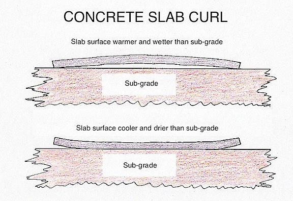
The damage location reflects the amount of moisture exposure.
If conditions exist that cause the edges to curl down or the middle of the slab to lift, a void can be created beneath the middle portions of the slab. If a load is applied to the unsupported section that exceeds the slab’s structural capacity, such as when a girder support post bears on the slab, the slab may fail, allowing the girder and the framing it supports to sag.
Blisters
Air trapped in the concrete matrix can find its way to the surface and become trapped beneath a dense layer of cement paste. This is most likely to happen when:
- the concrete has been poorly vibrated. Inadequate vibration prevents air trapped in the matrix from being released. Excessive vibration concentrates cement paste at the surface;
- the surface has been sealed by floating it with the wrong tool;
- finishing operations begin while bleed water is still rising. Conditions that encourage high evaporation rates may make it appear as though bleed water has stopped rising when that is not the case. Finishing concrete while bleed water is still rising will concentrate cement paste and fine aggregates at the surface; or
- high levels of air entrainment can extend the time needed for bleed water to finish rising, fooling workers into starting finishing operations too soon.
Dusting Concrete
When you run your finger over a concrete surface and it collects a coating of concrete dust, you have picked up loose powder that has formed as the surface has disintegrated. It’s called dusting or chalking. The surface will be soft and easily scratched. Dusting is most noticeable with floors because they experience traffic and wear.
Dusting can be caused by:
- performing finishing operations while bleed water is still on the surface. This can happen when bull-floating is delayed, or if finish troweling starts too soon. Working bleed water back into the top 1/4-inch of slab surface leaves this layer with a higher water-to-cement ratio than is proper and lowers its strength;
- finishing operations performed in cold weather. These operations can work condensation into the slab surface. Concrete sets slowly in cold weather, especially at basement floors. In areas with high humidity, such as the Pacific Northwest, condensation that forms on cool, newly poured concrete will cause dusting if it’s troweled into the surface;
- inadequate ventilation in enclosed spaces. The use of motors, as is common with mixers, generators and gasoline-powered finishing equipment, produces carbon dioxide, which can penetrate and react with the surface concrete to reduce its strength and durability;
- inadequate protection of newly placed concrete from rain, snow or drying winds. Allowing the surface concrete to freeze will weaken it. Although keeping surface concrete wet is advisable during the curing process, the timing has to be right. Too much moisture added too soon will result in dusting. Drying winds will cause the surface concrete to shrink much more quickly than the main underlying body of wet concrete. The differential shrinkage rate will cause surface cracking; and
- sprinkling cement on the surface. This is sometimes done to soak up excess bleed water and weakens the surface.
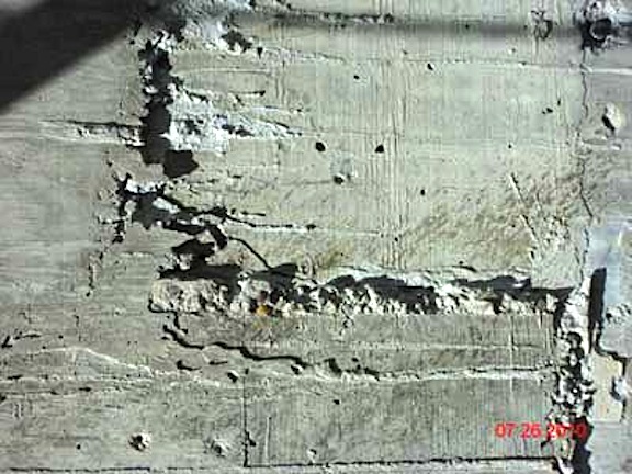
Parge Coats
A parge coat is a thin layer of mortar troweled onto the exterior of a masonry wall. The purpose may be to improve the appearance of the wall, or to hide functional or cosmetic damage. Functional damage is damage that may affect the structural integrity of the concrete wall. Cosmetic damage affects only its appearance. The concern for inspectors is that the parge coat may hide evidence of significant existing damage or of forces that may cause future structural damage. An example is cracking caused by expansive soils that may continue to expand and contract, with the potential to cause continuing damage.
A parge coat showing widespread pattern cracking from excessive water
in the mix or excessively fast drying, or both
The photo above shows a close-up of the parge coat.
The parge coat bond has failed and it has begun to delaminate from the underlying wall.
Cracks visible in a parge coat may be limited to the parge coat only, with the underlying concrete in sound condition, or cracks in the underlying concrete may have propagated through to the parge coat, since parge coats and concrete are bonded together. If cracks in the parge coat align with cracks on the opposite side of a concrete wall, chances are good that the crack originated with the concrete and extends completely through the concrete wall. A through crack is evidence of strong forces at work. If there are no cracks on a wall aligning with parge cracks on the opposite side, the cracks may still have originated with the concrete wall, but the wall has not cracked through, so such a condition is less serious.
Inspecting Concrete
The authors wish to thank InterNACHI member Marcel Cyr for his help in producing this article.
