Structural Design of Lateral Resistance to Wind and Earthquake for the Home Inspector
by Nick Gromicko, CMI® and Ben Gromicko
General
The objectives in designing a building’s lateral resistance to wind and earthquake forces are:
- to provide a system of shear walls, diaphragms, and interconnections to transfer lateral loads and overturning forces to the foundation;
- to prevent building collapse in extreme wind and seismic events; and
- to provide adequate stiffness to the structure for service loads experienced in moderate wind and seismic events.
Judgment is a crucial factor that comes into play when the designer selects how the building is to be analyzed and to what extent the analysis should be assumed to be a correct representation of the true design problem. Designer judgment is essential in the early stages of design because the analytic methods and assumptions used to evaluate the lateral resistance of light-frame buildings are not in themselves correct representations of the problem. They are analogies that are sometimes reasonable but at other times depart significantly from reason and actual system testing or field experience.
This article focuses on methods for evaluating the lateral resistance of individual sub-assemblies of the LFRS (i.e., shear walls and diaphragms) and the response of the whole building to lateral loads (i.e., load distribution). Traditional design approaches as well as innovative methods, such as the perforated shear wall design method, are integrated into the designer's toolbox. While the code-approved methods have generally worked, there is considerable opportunity for improvement and optimization. Therefore, the information and design examples presented in this article provide a useful guide and resource that supplement existing building code provisions. More importantly, the article is aimed at fostering a better understanding of the role of analysis versus judgment, and promoting more efficient design in the form of alternative methods.
The lateral design of light-frame buildings is not a simple endeavor that provides exact solutions. By the very nature of the LFRS, the real behavior of light-frame buildings is highly dependent on the performance of building systems, including the interactions of structural and nonstructural components. For example, the nonstructural components in conventional housing (i.e., sidings, interior finishes, interior partition walls, and even windows and trim) can account for more than 50 percent of a building’s lateral resistance. Yet, the contribution of these components is not considered as part of the designed LFRS for lack of appropriate design tools and building code provisions that may prohibit such considerations. In addition, the need for simplified design methods inevitably leads to a trade-off–analytical simplicity for design efficiency.
In seismic design, factors that translate into better performance may not always be obvious. The inspector should become accustomed to thinking in terms of the relative stiffness of components that make up the whole building. Important, too, is an understanding of the inelastic (nonlinear), nonrigid body behavior of wood-framed systems that affect the optimization of strength, stiffness, dampening, and ductility. In this context, the concept that more strength is better is insupportable without considering the impact on other important factors. Many factors relate to a structural system’s deformation capability and ability to absorb and safely dissipate energy from abusive cyclic motion in a seismic event. The intricate interrelationship of these several factors is difficult to predict with available seismic design approaches.
For example, the basis for the seismic response modifier R is a subjective representation of the behavior of a given structure or structural system in a seismic event. In a sense, it bears evidence of the inclusion of “fudge factors” in engineering science for reason of necessity (not of preference) in attempting to mimic reality. It is not necessarily surprising, then, that the amount of wall bracing in conventional homes shows no apparent correlation with the damage levels experienced in seismic events (HUD, 1999). Similarly, the near-field damage to conventional homes in the Northridge Earthquake did not correlate with the magnitude of response spectral ground accelerations in the short period range (HUD, 1999). The short-period spectral response acceleration, it will be recalled, is the primary ground motion parameter used in the design of most low-rise and light-frame buildings.
The apparent lack of correlation between design theory and actual outcome points to the tremendous uncertainty in existing seismic design methods for light-frame structures. In essence, a designer’s compliance with accepted seismic design provisions may not necessarily be a good indication of actual performance in a major seismic event. This statement may be somewhat unsettling but is worthy of mention. For wind design, the problem is not as severe in that the lateral load can be more easily treated as a static load, with system response primarily a matter of determining lateral capacity without complicating inertial effects, at least for small light-frame buildings.
Therefore, the inspector should have a reasonable knowledge of the underpinnings of current LFRS design approaches (including their uncertainties and limitations). However, many inspectors do not have the opportunity to become familiar with the experience gained from testing whole buildings or assemblies. Design provisions are generally based on an element-based approach to engineering and usually provide little guidance on the performance of the various elements as assembled in a real building. To this end, the next section presents a brief overview of several whole-house lateral load tests.
Overview of Whole-Building Tests
A growing number of full-scale tests of houses have been conducted to gain insight into actual system strength and structural behavior.
One whole-house test program investigated the lateral stiffness and natural frequency of a production-built home (Yokel, Hsi, and Somes, 1973). The study applied a design load simulating a uniform wind pressure of 25 psf to a conventionally built home: a two-story, split-foyer dwelling with a fairly typical floor plan. The maximum deflection of the building was only 0.04 inches and the residual deflection about 0.003 inches. The natural frequency and dampening of the building were 9 hz (0.11 s natural period) and 6 percent, respectively. The testing was nondestructive such that the investigation yielded no information on “post-yielding” behavior; however, the performance was good for the nominal lateral design loads under consideration.
Another whole-house test applied transverse loads without uplift to a wood-framed house. Failure did not occur until the lateral load reached the equivalent of a 220-mph wind event without inclusion of uplift loads (Tuomi and McCutcheon, 1974). The house was fully sheathed with 3/8-inch plywood panels, and the number of openings was somewhat fewer than would be expected for a typical home (at least on the street-facing side). The failure took the form of slippage at the floor connection to the foundation sill plate (i.e., there was only one 16d toenail at the end of each joist, and the band joist was not connected to the sill). The connection was somewhat less than what is now required in the United States for conventional residential construction (ICC, 1998). The racking stiffness of the walls nearly doubled from that experienced before the addition of the roof framing. In addition, the simple 2x4 wood trusses were able to carry a gravity load of 135 psf–more than three times the design load of 40 psf. However, it is important to note that combined uplift and lateral load, as would be expected in high-wind conditions, was not tested. Further, the test house was relatively small and boxy in comparison to modern homes.
Many whole-house tests have been conducted in Australia. In one series of whole-house tests, destructive testing has shown that conventional residential construction (only slightly different from that in the United States) was able to withstand 2.4 times its intended design wind load (corresponding to a 115-mph wind speed) without failure of the structure (Reardon and Henderson, 1996). The test house had typical openings for a garage, doors and windows, and no special wind-resistant detailing. The tests applied a simultaneous roof uplift load of 1.2 times the total lateral load. The drift in the two-story section was 3 mm at the maximum applied load, while the drift in the open one-story section (i.e., no interior walls) was 3 mm at the design load and 20 mm at the maximum applied load.
Again in Australia, a house with fiber cement exterior cladding and plasterboard interior finishes was tested to 4.75 times its design lateral load capacity (Boughton and Reardon, 1984). The walls were restrained with tie rods to resist wind uplift loads, as required in Australia’s typhoon-prone regions. The roof and ceiling diaphragm was found to be stiff; in fact, the diaphragm rigidly distributed the lateral loads to the walls. The tests suggested that the house had sufficient capacity to resist a design wind speed of 65 m/s (145 mph).
Yet another Australian test of a whole house found that the addition of interior ceiling finishes reduced the deflection (i.e., drift) of one wall line by 75 percent (Reardon, 1988; Reardon, 1989). When cornice trim was added to cover or dress the wall-ceiling joint, the deflection of the same wall was reduced by another 60 percent (roughly 16 percent of the original deflection). The tests were conducted at relatively low load levels to determine the impact of various nonstructural components on load distribution and stiffness.
Recently, several whole-building and assembly tests in the United States have been conducted to develop and validate sophisticated finite-element computer models (Kasal, Leichti, and Itani, 1994). Despite some advances in developing computer models as research tools, the formulation of a simplified methodology for application by designers lags behind. Moreover, the computer models tend to be time-intensive to operate and require detailed input for material and connection parameters that would not normally be available to typical designers. Given the complexity of system behavior, the models are often not generally applicable and require recalibration whenever new systems or materials are specified.
In England, researchers have taken a somewhat different approach by moving directly from empirical system data to a simplified design methodology, at least for shear walls (Griffiths and Wickens, 1996). This approach applies various system factors to basic shear wall design values to obtain a value for a specific application. System factors account for material effects in various wall assemblies, wall configuration effects (i.e., number of openings in the wall), and interaction effects with the whole building. One factor even accounts for the fact that shear loads on wood-framed shear walls in a full brick-veneered building are reduced by as much as 45 percent for wind loads, assuming, of course, that the brick veneer is properly installed and detailed to resist wind pressures.
More recently, whole-building tests have been conducted in Japan (and to a lesser degree in the United States) by using large-scale shake tables to study the inertial response of whole light-frame buildings (Yasumura, 1999). The tests have demonstrated whole-building stiffness of about twice that experienced by walls tested independently. The results are reasonably consistent with those reported above. Apparently, many whole-building tests have been conducted in Japan, but the associated reports are available only in Japanese (Thurston, 1994).
The growing body of whole-building test data will likely improve the understanding of the actual performance of light-frame structures in seismic events to the extent that the test programs are able to replicate actual conditions. Actual performance must also be inferred from anecdotal experience or, preferably, from experimentally designed studies of buildings experiencing major seismic or wind events.
LFRS Design Steps and Terminology
The lateral force resisting system (LFRS) of a home is the whole house, including practically all structural and non-structural components. To enable a rational and tenable design analysis; however, the complex structural system of a light-frame house is usually subjected to many simplifying assumptions.
The steps required for thoroughly designing a building’s LFRS are outlined below in typical order of consideration:
- Determine a building’s architectural design, including layout of walls and floors (usually pre-determined).
- Calculate the lateral loads on the structure resulting from wind and/or seismic conditions.
- Distribute shear loads to the LFRS (wall, floor, and roof systems).
- Determine shear wall and diaphragm assembly requirements for the various LFRS components (sheathing thickness, fastening schedule, etc.) to resist the stresses resulting from the applied lateral forces.
- Design the hold-down restraints required to resist overturning forces generated by lateral loads applied to the vertical components of the LFRS (i.e., shear walls).
- Determine interconnection requirements to transfer shear between the LFRS components (i.e., roof, walls, floors and foundation).
- Evaluate chords and collectors (or drag struts) for adequate capacity and for situations requiring special detailing, such as splices.
It should be noted that, depending on the method of distributing shear loads, Step 3 may be considered a preliminary design step. If, in fact, loads are distributed according to stiffness in Step 3, then the LFRS must already be defined; therefore, the above sequence can become iterative between Steps 3 and 4. A designer need not feel compelled to go to such a level of complexity (i.e., using a stiffness-based force distribution) in designing a simple home, but the decision becomes less intuitive with increasing plan complexity.
The above list of design steps introduced several terms that are defined below.
Horizontal diaphragms are assemblies, such as the roof and floors, that act as deep beams by collecting and transferring lateral forces to the shear walls, which are the vertical components of the LFRS. The diaphragm is analogous to a horizontal, simply supported beam laid flatwise; a shear wall is analogous to a vertical, fixed-end, cantilevered beam.
Chords are the members (or a system of members) that form a flange to resist the tension and compression forces generated by the beam action of a diaphragm or shear wall. As shown in Figure 1, the chord members in shear walls and diaphragms are different members, but they serve the same purpose in the beam analogy. A collector or drag strut, which is usually a system of members in light-frame buildings, collects and transfers loads by tension or compression to the shear resisting segments of a wall line.
In typical light-frame homes, special design of chord members for floor diaphragms may involve some modest detailing of splices at the diaphragm boundary (i.e., joints in the band joists). If adequate connection is made between the band joist and the wall top plate, then the diaphragm sheathing, band joists, and wall framing function as a composite chord in resisting the chord forces. Thus, the diaphragm chord is usually integral with the collectors or drag struts in shear walls. Given that the collectors on shear walls often perform a dual role as a chord on a floor or roof diaphragm boundary, the designer needs only to verify that the two systems are reasonably interconnected along their boundary, thus ensuring composite action as well as direct shear transfer (i.e., slip resistance) from the diaphragm to the wall. As shown in Figure 2, the failure plane of a typical composite collector or diaphragm chord can involve many members and their interconnections.
For shear walls in typical light-frame buildings, tension and compression forces on shear wall chords are usually considered. In particular, the connection of hold-downs to shear wall chords should be carefully evaluated with respect to the transfer of tension forces to the structure below. Tension forces result from the overturning action (i.e., overturning moment) caused by the lateral shear load on the shear wall. In some cases, the chord may be required to be a thicker member to allow for an adequate hold-down connection or to withstand the tension and compression forces presumed by the beam analogy. Fortunately, most chords in light-frame shear walls are located at the ends of walls or adjacent to openings where multiple studs are already required for reasons of constructability and gravity load resistance (see cross-section "B" in Figure 1).
Figure 1. Chords in Shear Walls and Horizontal Diaphragms Using the Deep Beam Analogy
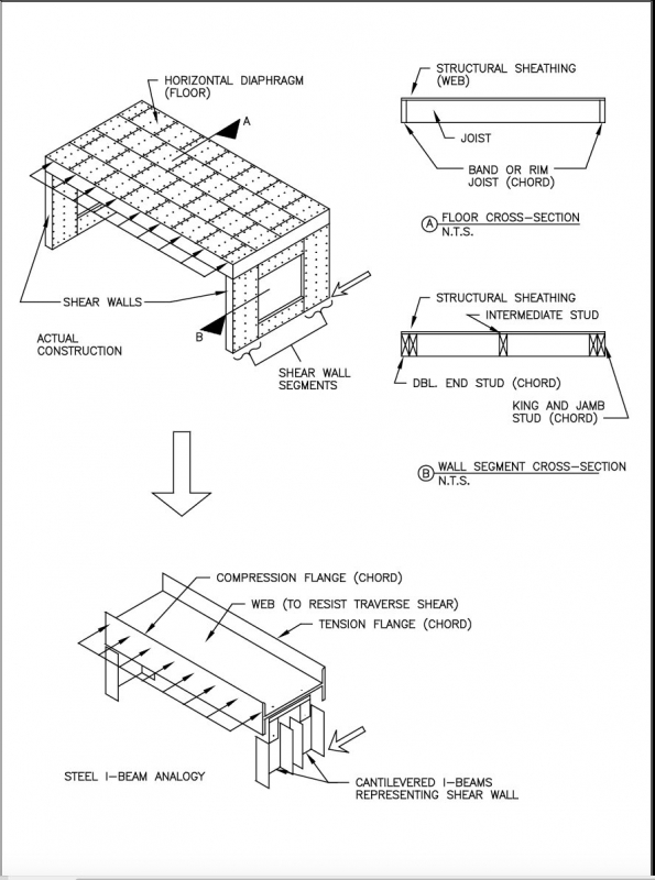
Figure 2. Shear Wall Collector and the Composite Failure Plane (Failure plane also applies to diaphragm chords.)

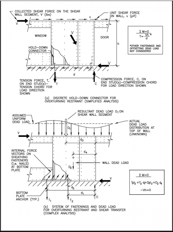
Hold-down restraints are devices used to restrain the whole building and individual shear wall segments from the overturning that results from the leveraging (i.e., overturning moment) created by lateral forces. The current engineering approach calls for restraints that are typically metal connectors (i.e., straps or brackets) that attach to and anchor the chords (i.e., end studs) of shear wall segments (see Figure 3). In many typical residential applications, however, overturning forces may be resisted by the dead load and the contribution of many component connections (see Figure 3). Unfortunately (in reality), this consideration may require a more intensive analytic effort and greater degree of designer presumption because overturning forces may disperse through many load paths in a nonlinear fashion. Consequently, the analysis of overturning becomes much more complicated; the designer cannot simply assume a single load path through a single hold-down connector. Indeed, analytic knowledge of overturning has not matured sufficiently to offer an exact performance-based solution, even though experience suggests that the resistance provided by conventional framing has proven adequate to prevent collapse in all but the most extreme conditions or misapplications.
Framing and fastenings at wall corner regions are a major factor in explaining the actual behavior of conventionally built homes, yet there is no currently recognized way to account for this effect from a performance-based design perspective. Several studies have investigated corner-framing effects in restraining shear walls without the use of hold-down brackets. In one such study, cyclic and monotonic tests of typical 12-foot-long wood-framed shear walls with 2- and 4-foot corner returns have demonstrated that overturning forces can be resisted by reasonably detailed corners (i.e., sheathing fastened to a common corner stud), with the reduction in shear capacity only about 10 percent from that realized in tests of walls with hold-downs instead of corner returns (Dolan and Heine, 1997c). The corner framing approach can also improve ductility (Dolan and Heine, 1997c) and is confirmed by testing in other countries (Thurston, 1994). In fact, shear wall test methods in New Zealand use a simple three-nail connection to provide hold-down restraint (roughly equivalent to three 16d common nails in a single shear wood-to-wood connection with approximately a 1,200- to 1,500-pound ultimate capacity). The three-nail connection resulted from an evaluation of the restraining effect of corners and the selection of a minimum value from typical construction. The findings of the tests reported above do not consider the beneficial contribution of the dead load in helping to restrain a corner from uplift as a result of overturning action.
The discussion to this point has given some focus to conventional residential construction practices for wall bracing that have worked effectively in typical design conditions. This observation is a point of contention, however, because conventional construction lacks the succinct loads paths that may be assumed when following an accepted engineering method. Therefore, conventional residential construction does not lend itself readily to current engineering conventions of analyzing a lateral force resisting system in light-frame construction. As a result, it is difficult to define appropriate limitations to the use of conventional construction practices based purely on existing conventions of engineering analysis.
Figure 3. Two Types of Hold-Down Restraint and Basic Analytic Concepts
The Current LFRS Design Practice
This section provides a brief overview of the current design practices for analyzing the LFRS of light-frame buildings. It highlights the advantages and disadvantages of the various approaches but, in the absence of a coherent body of evidence, makes no attempt to identify which approach, if any, may be considered superior. Where experience from whole-building tests and actual building performance in real events permits, the discussion provides a critique of current design practices that, for lack of better methods, relies somewhat on an intuitive sense for the difference between the structure as it is analyzed and the structure as it may actually perform. The intent is not to downplay the importance of engineering analysis; rather, the designer should understand the implications of the current analytic methods and their inherent assumptions and then put them into practice in a suitable manner.
Lateral Force Distribution Methods
The design of the LFRS of light-frame buildings generally follows one of three methods described below. Each differs in its approach to distributing whole-building lateral forces through the horizontal diaphragms to the shear walls. Each varies in the level of calculation, precision, and dependence on designer judgment. While different solutions can be obtained for the same design by using the different methods, one approach is not necessarily preferred to another. All may be used for the distribution of seismic and wind loads to the shear walls in a building. However, some of the most recent building codes may place limitations or preferences on certain methods.
Tributary Area Approach (Flexible Diaphragm)
The tributary area approach is perhaps the most popular method used to distribute lateral building loads. Tributary areas based on building geometry are assigned to various components of the LFRS to determine the wind or seismic loads on building components (i.e., shear walls and diaphragms). The method assumes that a diaphragm is relatively flexible in comparison to the shear walls (i.e., a flexible diaphragm) such that it distributes forces according to tributary areas rather than according to the stiffness of the supporting shear walls. This hypothetical condition is analogous to conventional beam theory, which assumes rigid supports, as illustrated in Figure 4 for a continuous horizontal diaphragm (i.e., floor) with three supports (i.e., shear walls).
Figure 4 Lateral Force Distribution by a Flexible Diaphragm (tributary area approach)

In seismic design, tributary areas are associated with uniform area weights (i.e., dead loads) assigned to the building systems (i.e., roof, walls and floors) that generate the inertial seismic load when the building is subject to lateral ground motion. In wind design, the tributary areas are associated with the lateral component of the wind load acting on the exterior surfaces of the building.
The flexibility of a diaphragm depends on its construction, as well as on its aspect ratio (length:width). Long narrow diaphragms, for example, are more flexible in bending along the their long dimension than short wide diaphragms. In other words, rectangular diaphragms are relatively stiff in one loading direction and relatively flexible in the other. Similarly, long shear walls with few openings are stiffer than walls comprised of only narrow shear wall segments. While analytic methods are available to calculate the stiffness of shear wall segments and diaphragms, the actual stiffness of these systems is extremely difficult to predict accurately. It should be noted that if the diaphragm is considered infinitely rigid relative to the shear walls and the shear walls have roughly equivalent stiffness, the three shear wall reactions will be roughly equivalent. If this assumption were more accurate, the interior shear wall would be over-designed and the exterior shear walls under-designed with use of the tributary area method. In many cases, the correct answer is probably somewhere between the apparent over- and under-design conditions.
The tributary area approach is reasonable when the layout of the shear walls is generally symmetrical with respect to even spacing and similar strength and stiffness characteristics. It is particularly appropriate in concept for simple buildings with diaphragms supported by two exterior shear wall lines (with similar strength and stiffness characteristics) along both major building axes. More generally, the major advantages of the tributary area LFRS design method are its simplicity and applicability to simple building configurations. In more complex applications, the designer should consider possible imbalances in shear wall stiffness and strength that may cause or rely on torsional response to maintain stability under lateral load (see relative stiffness design approach).
Total Shear Approach (“Eyeball” Method)
Considered the second most popular and simplest of the three LFRS design methods, the total shear approach uses the total story shear to determine a total amount of shear wall length required on a given story level for each orthogonal direction of loading. The amount of shear wall is then evenly distributed in the story according to designer judgment. While the total shear approach requires the least amount of computational effort among the three methods, it demands good “eyeball” judgment as to the distribution of the shear wall elements in order to address or avoid potential loading or stiffness imbalances. In seismic design, loading imbalances may be created when a building’s mass distribution is not uniform. In wind design, loading imbalances result when the surface area of the building is not uniform (i.e., taller walls or steeper roof sections experience greater lateral wind load). In both cases, imbalances are created when the center of resistance is offset from either the center of mass (seismic design) or the resultant force center of the exterior surface pressures (wind design). Thus, the reliability of the total shear approach is highly dependent on the designer’s judgment and intuition regarding load distribution and structural response. If used indiscriminately without consideration of the above factors, the total shear approach to LFRS design can result in poor performance in severe seismic or wind events. However, for small structures such as homes, the method has produced reasonable designs, especially in view of the overall uncertainty in seismic and wind load analysis.
Relative Stiffness Design Approach (Rigid Diaphragm)
The relative stiffness approach was first contemplated for house design in the 1940s and was accompanied by an extensive testing program to create a database of racking stiffnesses for a multitude of interior and exterior wall constructions used in residential construction at that time (NBS, 1948). If the horizontal diaphragm is considered stiff relative to the shear walls, then the lateral forces on the building are distributed to the shear wall lines according to their relative stiffness. A stiff diaphragm may then rotate some degree to distribute loads to all walls in the building, not just to walls parallel to an assumed loading direction. Thus, the relative stiffness approach considers torsional load distribution as well as distribution of the direct shear loads. When torsional force distribution needs to be considered, whether to demonstrate lateral stability of an unevenly braced building or to satisfy a building code requirement, the relative stiffness design approach is the only available option.
Although the approach is conceptually correct and comparatively more rigorous than the other two methods, its limitations with respect to reasonably determining the real stiffness of shear wall lines (composed of several restrained and unrestrained segments and nonstructural components) and diaphragms (also affected by nonstructural components and the building plan configuration) render its analogy to actual structural behavior uncertain. Ultimately, it is only as good as the assumptions regarding the stiffness or shear walls and diaphragms relative to the actual stiffness of a complete building system. As evidenced in the previously mentioned whole-building tests and in other authoritative design texts on the subject (Ambrose and Vergun, 1987), difficulties in accurately predicting the stiffness of shear walls and diaphragms in actual buildings are significant. Moreover, unlike the other methods, the relative stiffness design approach is iterative in that the distribution of loads to the shear walls requires a preliminary design so that relative stiffness may be estimated. One or more adjustments and recalculations may be needed before reaching a satisfactory final design.
However, it is instructional to consider analytically the effects of stiffness in the distribution of lateral forces in an LFRS, even if based on somewhat idealized assumptions regarding relative stiffness (i.e., diaphragm is rigid over the entire expanse of shear walls). The approach is a reasonable tool when the torsional load distribution should be considered in evaluating or demonstrating the stability of a building, particularly a building that is likely to undergo significant torsional response in a seismic event. Indeed, torsional imbalances exist in just about any building and may be responsible for the relatively good performance of some light-frame homes when one side (i.e., the street-facing side of the building) is weaker (i.e., less stiff and less strong) than the other three sides of the building. This condition is common owing to the aesthetic desire and functional need for more openings on the front side of a building. However, a torsional response in the case of under-design (i.e., weak or “soft” story) can wreak havoc on a building and constitute a serious threat to life.
Shear Wall Design Approaches
Once the whole-building lateral loads have been distributed and assigned to the floor and roof diaphragms and various designated shear walls, each of these subassemblies must be designed to resist the assigned shear loads. As discussed, the whole-building shear loads are distributed to various shear walls ultimately in accordance with the principle of relative stiffness (whether handled by judgment, analytic assumptions per a selected design method, or both). Similarly, the distribution of the assigned shear load to the various shear wall segments within a given shear wall line is based on the same principle, but at a different scale. The scale is the subassembly (or shear wall) as opposed to the whole building.
The methods for designing and distributing the forces within a shear wall line differ as described below. As with the three different approaches described for the distribution of lateral building loads, the shear wall design methods place different levels of emphasis on analytic rigor and judgment. Ultimately, the configuration of the building (i.e., Are the walls inherently broken into individual segments by large openings or many offsets in plan dimensions?) and the required demand (i.e., shear load) should drive the choice of a shear wall design approach and the resulting construction detailing. Thus, the choice of which design method to use is a matter of designer judgment and required performance. In turn, the design method itself imposes detailing requirements on the final construction in compliance with the analysis assumptions. Accordingly, the above decisions affect the efficiency of the design effort and the complexity of the resulting construction details.
Segmented Shear Wall (SSW) Design Approach
The segmented shear wall design approach, well-recognized as a standard design practice, is the most widely used method of shear wall design. It considers the shear resisting segments of a given shear wall line as separate elements, with each segment restrained against overturning by the use of hold-down connectors at its ends. Each segment is a fully sheathed portion of the wall without any openings for windows or doors. The design shear capacity of each segment is determined by multiplying the length of the segment (sometimes called segment width) by tabulated unit shear design values that are available in the building codes and newer design standards. In its simplest form, the approach analyzes each shear wall segment for static equilibrium in a manner analogous to a cantilevered beam with a fixed end (refer to Figures 1 and 3). In a wall with multiple designated shear wall segments, the typical approach to determining an adequate total length of all shear wall segments is to divide the design shear load demand on the wall by the unit shear design value of the wall construction. The effect of stiffness on the actual shear force distribution to the various segments is simply handled by complying with code-required maximum shear wall segment aspect ratios (i.e., segment height divided by segment width). Although an inexact and circuitous method of handling the problem of shear force distribution in a shear wall line, the SSW approach has been in successful practice for many years, partly due to the use of conservative unit shear design values.
When stiffness is considered, the stiffness of a shear wall segment is assumed to be linearly related to its length (or its total design shear strength). However, the linear relationship is not realistic outside certain limits. For example, stiffness begins to decrease with notable nonlinearly once a shear wall segment decreases below a 4-foot length on an 8-foot-high wall (i.e., aspect ratio of 2 or greater). This does not mean that wall segments shorter than 4 feet in width cannot be used but, rather, that the effect of relative stiffness in distributing the load needs to be considered. The SSW approach is also less favorable when the wall as a system rather than individual segments (i.e., including sheathed areas above and below openings) may be used to economize on design while meeting required performance (see perforated shear wall design approach below).
As shown in Figure 3, it is common either to neglect the contribution of dead load or assume that the dead load on the wall is uniformly distributed as would be the case under gravity loading only. In fact, unless the wall is restrained with an infinitely rigid hold-down device (an impossibility), the uniform dead load distribution will be altered as the wall rotates and deflects upward during the application of shear force (see Figure 3). As a result, depending on the rigidity of the framing system above, the dead load will tend to concentrate more toward the high points in the wall line, as the various segments begin to rotate and uplift at their leading edges. Thus, the dead load may be somewhat more effective in offsetting the overturning moment on a shear wall segment than is suggested by the uniform dead load assumption. Unfortunately, this phenomenon involves nonrigid body, nonlinear behavior for which there are no simplified methods of analysis. Therefore, this effect is generally not considered, particularly for walls with specified restraining devices (i.e., hold-downs) that are, by default, generally assumed to be completely rigid–an assumption that is known by testing not to hold true to varying degrees depending on the type of device and its installation.
Basic Perforated Shear Wall (PSW) Design Approach
The basic perforated shear wall (PSW) design method is gaining popularity among designers and even earning code recognition. The method, however, is not without controversy in terms of appropriate limits and guidance on use. A perforated shear wall is a wall that is fully sheathed with wood structural panels (i.e., oriented strand board or plywood) and that has openings or perforations for windows and doors. The ends of the walls−rather than each individual segment as in the segmented shear wall method−are restrained against overturning. As for the intermediate segments of the wall, they are restrained by conventional or designed framing connections, such as those at the base of the wall that transfer the shear force resisted by the wall to the construction below. The capacity of a PSW is determined as the ratio of the strength of a wall with openings to the strength of a wall of the same length without openings. Figure 5 illustrates a perforated shear wall.
Figure 5. Illustration of a Basic Perforated Shear Wall

The PSW design method requires the least amount of special construction detailing and analysis among the current shear wall design methods. It has been validated in several recent studies in the United States but dates back more than 20 years to research first conducted in Japan (Dolan and Heine, 1997a and b; Dolan and Johnson, 1996a and 1996b; NAHBRC, 1997; NAHBRC, 1998; NAHBRC, 1999; Sugiyama and Matsumoto, 1994; Ni et al., 1998). While it produces the simplest form of an engineered shear wall solution, other methods, such as the segmented shear wall design method–all other factors being equal–can yield a stronger wall. Conversely, a PSW design with increased sheathing fastening can out-perform an SSW with more hold-downs but weaker sheathing fastening. The point is, that for many applications, the PSW method often provides an adequate and more efficient design. Therefore, the PSW method should be considered an option to the SSW method as appropriate.
Enhancements to the PSW Approach
Several options in the form of structural optimizations (getting the most from the least) can enhance the PSW method. One option uses multiple metal straps or ties to restrain each stud, thereby providing a highly redundant and simple method of overturning restraint. Unfortunately, this promising enhancement has been demonstrated in only one known proof test of the concept (NAHBRC, 1999). It can, however, improve shear wall stiffness and increase capacity beyond that achieved with either the basic PSW method or SSW design approach. Another option, subjected to limited study by the NAHB Research Center, calls for perforated shear walls with metal truss plates at key framing joints (NAHBRC, 1998). To a degree similar to that in the first option, this enhancement increases shear capacity and stiffness without the use of any special hold-downs or restraining devices other than conventional framing connections at the base of the wall (i.e., nails or anchor bolts). Neither of the above options applied dead loads to the tested walls, such application would have improved performance. Unfortunately, the results do not lend themselves to easy duplication by analysis and must be used at their face value as empirical evidence to justify practical design improvements for conditions limited by the tests. Analytic methods are under development to facilitate use of optimization concepts in shear wall design and construction.
In a mechanics-based form of the PSW, analytic assumptions using free-body diagrams and principles of statics can conservatively estimate restraining forces that transfer shear around openings in shear walls based on the assumption that wood-framed shear walls behave as rigid bodies with elastic behavior. As compared to several tests of the perforated shear wall method discussed above, the mechanics-based approach leads to a conservative solution requiring strapping around window openings. In a condition outside the limits for application of the PSW method, a mechanics-based design approach for shear transfer around openings provides a reasonable alternative to traditional SSW design and the newer empirically based PSW design. The added detailing merely takes the form of horizontal strapping and blocking at the top and bottom corners of window openings to transfer the calculated forces derived from free-body diagrams representing the shear wall segments and sheathed areas above and below openings. For more detail, the reader should consult other sources of information on this approach (Diekmann, 1986; ICBO, 1997; ICC, 1999).
Basic Diaphragm Design Approach
As described earlier in this article, horizontal diaphragms are designed by using the analogy of a deep beam laid flatwise. Thus, the shear forces in the diaphragm are calculated as for a beam under a uniform load (refer to Figure 4). As is similar to the case of shear walls, the design shear capacity of a horizontal diaphragm is determined by multiplying the diaphragm depth (i.e., depth of the analogous deep beam) by the tabulated unit shear design values found in building codes. The chord forces (in the flange of the analogous deep beam) are calculated as a tension force and compression force on opposite sides of the diaphragm. The two forces form a force couple (i.e., moment) that resists the bending action of the diaphragm (refer to Figure 1).
To simplify the calculation, it is common practice to assume that the chord forces are resisted by a single chord member serving as the flange of the deep beam (i.e., a band joist). At the same time, bending forces internal to the diaphragm are assumed to be resisted entirely by the boundary member or band joist, rather than by other members and connections within the diaphragm. In addition, other parts of the diaphragm boundary (i.e., walls) that also resist the bending tension and compressive forces are not considered. Certainly, a vast majority of residential roof diaphragms that are not considered engineered by current diaphragm design standards have exhibited ample capacity in major design events. Thus, the beam analogy used to develop an analytic model for the design of wood-framed horizontal diaphragms has room for improvement that has yet to be explored from an analytic standpoint.
As with shear walls, openings in the diaphragm affect the diaphragm’s capacity. However, no empirical design approach accounts for the effect of openings in a horizontal diaphragm as for shear walls (i.e., the PSW method). Therefore, if openings are present, the effective depth of the diaphragm in resisting shear forces must either discount the depth of the opening or be designed for shear transfer around the opening. If it is necessary to transfer shear forces around a large opening in a diaphragm, it is common to perform a mechanics-based analysis of the shear transfer around the opening. The analysis is similar to the previously described method that uses free-body diagrams for the design of shear walls. The reader is referred to other sources for further study of diaphragm design (Ambrose and Vergun, 1987; APA, 1997; Diekmann, 1986).
Design Guidelines
General Approach
This section outlines methods for designing shear walls and diaphragms. The two methods of shear wall design are the segmented shear wall (SSW) method and the perforated shear wall (PSW) method. The selection of a method depends on shear loading demand, wall configuration, and the desired simplicity of the final construction. Regardless of design method and resulting LFRS, the first consideration is the amount of lateral load to be resisted by the arrangement of shear walls and diaphragms in a given building. The design loads and basic load are as follows:
- 0.6D + (W or 0.7E) ASD
- 0.9D + (1.5W or 1.0E) LRFD
Earthquake load and wind load are considered separately, with shear walls designed in accordance with more stringent loading conditions.
Lateral building loads should be distributed to the shear walls on a given story by using one of the following methods as deemed appropriate by the designer:
- tributary area approach;
- total shear approach; or
- relative stiffness approach.
These methods were described earlier. In the case of the tributary area method, the loads can be immediately assigned to the various shear wall lines based on tributary building areas (exterior surface area for wind loads and building plan area for seismic loads) for the two orthogonal directions of loading (assuming rectangular-shaped buildings and relatively uniform mass distribution for seismic design). In the case of the total shear approach, the load is considered as a “lump sum” for each story for both orthogonal directions of loading. The shear wall construction and total amount of shear wall for each direction of loading and each shear wall line are then determined in accordance with this section to meet the required load as determined by either the tributary area or total shear approach. The designer must be reasonably confident that the distribution of the shear walls and their resistance is reasonably balanced with respect to building geometry and the center of the total resultant shear load on each story. As mentioned, both the tributary and total shear approaches have produced many serviceable designs for typical residential buildings, provided that the designer exercises sound judgment.
In the case of the relative stiffness method, the assignment of loads must be based on an assumed relationship describing the relative stiffness of various shear wall lines. Generally, the stiffness of a wood-framed shear wall is assumed to be directly related to the length of the shear wall segments and the unit shear value of the wall construction. For the perforated shear wall method, the relative stiffness of various perforated shear wall lines may be assumed to be directly related to the design strength of the various perforated shear wall lines. Using the principle of moments and a representation of wall racking stiffness, the designer can then identify the center of shear resistance for each story and determine each story’s torsional load (due to the offset of the load center from the center of resistance). Finally, the designer superimposes direct shear loads and torsional shear loads to determine the estimated shear loads on each of the shear wall lines.
It is common practice (and required by some building codes) for the torsional load distribution to be used only to add to the direct shear load on one side of the building but not to subtract from the direct shear load on the other side, even though the restriction is not conceptually accurate. Moreover, most seismic design codes require evaluations of the lateral resistance to seismic loads with artificial or accidental offsets of the estimated center of mass of the building (i.e., imposition of an accidental torsional load imbalance). These provisions, when required, are intended to conservatively address uncertainties in the design process that may otherwise go undetected in any given analysis (i.e., building mass is assumed uniform when it actually is not). As an alternative, uncertainties may be more easily accommodated by increasing the shear load by an equivalent amount in effect (say, 10 percent). Indeed, the seismic shear load using the simplified method includes a factor that increases the design load by 20 percent and may be considered adequate to address uncertainties in torsional load distribution. However, the simple “20 percent” approach to addressing accidental torsion loads is not explicitly permitted in any current building code. But, for housing, where many redundancies also exist, the “20 percent” rule seems to be a reasonable substitute for a more exact analysis of accidental torsion. Of course, it is not a substitute for evaluating and designing for torsion that is expected to occur.
Shear Wall Design
Shear Wall Design Values (Fs)
This section provides unfactored (ultimate) unit shear values for wood-framed shear wall constructions that use wood structural panels. Other wall constructions and framing methods are included as an additional resource. The unit shear values given here differ from those in the current codes in that they are based explicitly on the ultimate shear capacity as determined through testing. Therefore, the designer is referred to the applicable building code for code-approved unit shear values. This guide uses ultimate unit shear capacities as its basis to give the designer an explicit measure of the actual capacity and safety margin (i.e., reserve strength) used in design and to provide for a more consistent safety margin across various shear wall construction options. Accordingly, it is imperative that the values used in this article are appropriately adjusted to ensure an acceptable safety margin.
Wood Structural Panels (WSP)
Table 1 provides unit shear values for walls sheathed with wood structural panels. It should be noted again that these values are estimates of the ultimate unit shear capacity values, as determined from several sources (Tissell, 1993; FEMA, 1997; NAHBRC, 1998; NAHBRC, 1999; others). The design unit shear values in today’s building codes have inconsistent safety margins that typically range from 2.5 to 4 after all applicable adjustments (Tissell, 1993; Soltis, Wolfe, and Tuomi, 1983). Therefore, the actual capacity of a shear wall is not explicitly known to the designer using the codes’ allowable unit shear values. Nonetheless, one alleged benefit of using the code-approved design unit shear values is that the values are believed to address drift implicitly by way of a generally conservative safety margin. Even so, shear wall drift is usually not analyzed in residential construction for reasons stated previously.
The values in Table 1 and today’s building codes are based primarily on monotonic tests (i.e., tests that use single-direction loading). Recently, the effect of cyclic loading on wood-framed shear wall capacity has generated considerable controversy. However, cyclic testing is apparently not necessary when determining design values for seismic loading of wood-framed shear walls with structural wood panel sheathing. Depending on the cyclic test protocol, the resulting unit shear values can be above or below those obtained from traditional monotonic shear wall test methods (ASTM, 1998a; ASTM, 1998b). In fact, realistic cyclic testing protocols and their associated interpretations were found to be largely in agreement with the results obtained from monotonic testing (Karacabeyli and Ceccotti, 1998). The differences are generally in the range of 10 percent (plus or minus) and thus seem moot given that the seismic response modifier is based on expert opinion (ATC, 1995) and that the actual performance of light-frame homes does not appear to correlate with important parameters in existing seismic design methods (HUD, 1999), among other factors that currently contribute to design uncertainty.
TABLE 1. Unfactored (Ultimate) Shear Resistance (plf) for Wood Structural Panel Shear Walls with Framing of Douglas Fir, Larch, or Southern Pine

The unit shear values in Table 1 are based on nailed sheathing connections. The use of elastomeric glue to attach wood structural panel sheathing to wood framing members increases the shear capacity of a shear wall by as much as 50 percent or more (White and Dolan, 1993). Similarly, studies using elastomeric construction adhesive manufactured by 3M Corporation have investigated seismic performance (i.e., cyclic loading) and confirm a stiffness increase of about 65 percent and a shear capacity increase of about 45 to 70 percent over sheathing fastened with nails only (Filiatrault and Foschi, 1991). Rigid adhesives may create even greater strength and stiffness increases. The use of adhesives is beneficial in resisting shear loads from wind. Glued shear wall panels are not recommended for use in high-hazard seismic areas because of the brittle failure mode experienced in the wood framing material (i.e., splitting), though at a significantly increased shear load. Gluing shear wall panels is also not recommended by panel manufacturers because of concern with panel buckling that may occur as a result of the interaction of rigid restraints with moisture/temperature expansion and contraction of the panels.
However, construction adhesives are routinely used in floor diaphragm construction to increase the bending stiffness and strength of floors; in-plane (diaphragm) shear is probably affected by an amount similar to that reported above for shear walls.
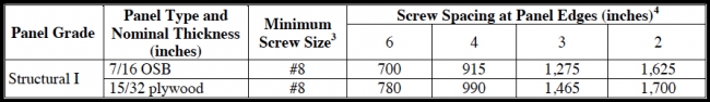
For unit shear values of wood structural panels applied to cold-formed steel framing, the following references are suggested: Uniform Building Code (ICBO,1997); Standard Building Code (SBCCI, 1999); and Shear Wall Values for Lightweight Steel Framing (AISI, 1996). The unit shear values for cold-formed steel-framed walls in the previous references are consistent with the values used in Table 1, including the recommended safety factor or resistance factor. Table 2 presents some typical unit shear values for cold-formed steel-framed walls with wood structural panel sheathing fastened with #8 screws. Values for power-driven, knurled pins (similar to deformed shank nails) should be obtained from the manufacturer and the applicable code evaluation reports (NES, Inc., 1997).
TABLE 2. Unfactored (Ultimate) Unit Shear Resistance (plf) for Walls with Cold-Formed Steel Framing and Wood Structural Panels
Portland Cement Stucco (PCS)
Ultimate unit shear values for conventional PCS wall construction range from 490 to 1,580 plf, based on the ASTM E 72 test protocol and 12 tests conducted by various testing laboratories (Testing Engineers, Inc., 1971; Testing Engineers, Inc., 1970; ICBO, 1969). In general, nailing the metal lath or wire mesh resulted in ultimate unit shear values less than 750 plf, whereas stapling resulted in ultimate unit shear values greater than 750 plf. An ultimate design value of 500 plf is recommended unless specific details of PCS construction are known. A safety factor of 2 provides a conservative allowable design value of about 250 plf. It must be realized that the actual capacity can be as much as five times 250 plf, depending on the method of construction, particularly the means of fastening the stucco lath material. Current code-approved allowable design values are typically about 180 plf (SBCCI, 1999; ICBO, 1997). One code requires the values to be further reduced by 50 percent in higher-hazard seismic design areas (ICBO, 1997), although the reduction factor may not necessarily improve performance with respect to the cracking of the stucco finish in seismic events (HUD, 1999). It may be more appropriate to use a lower seismic response modifier R than to increase the safety margin in a manner that is not explicit to the designer. In fact, an R factor for PCS wood-framed walls is not explicitly provided in building codes (perhaps an R of 4.5 for other wood-framed walls is used) and should probably be in the range of 3 to 4 (without additional increases in the safety factor), since some ductility is provided by the metal lath and its connection to wood framing.
The above values pertain to PCS that is 7/8-inch thick with nail or staple fasteners spaced 6 inches on-center for attaching the metal wire mesh or lath to all framing members. Nails are typically 11-gauge by 1-1/2 inches in length and staples typically have 3/4-inch leg and 7/8-inch crown dimensions. The above unit shear values also apply to stud spacings no greater than 24 inches on-center. Finally, the aspect ratio of stucco wall segments included in a design shear analysis should not be greater than 2 (height/width) according to current building code practice.
Gypsum Wall Board (GWB)
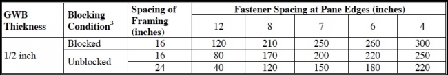
Ultimate capacities in testing 1/2-inch-thick gypsum wall board range from 140 to 300 plf, depending on the fastening schedule (Wolfe, 1983; Patton-Mallory, Gutkowski, Soltis, 1984; NAHBRF, date unknown). Allowable or design unit shear values for gypsum wall board sheathing range from 75 to 150 plf in current building codes, depending on the construction and fastener spacing. At least one building code requires the values to be reduced by 50 percent in high-hazard seismic design areas (ICBO, 1997). Gypsum wall board is certainly not recommended as the primary seismic bracing for walls, although it does contribute to the structural resistance of buildings in all seismic and wind conditions. It should also be recognized that fastening of interior gypsum board varies in practice and is generally not an inspected system. Table 3 provides estimated ultimate unit shear values for gypsum wall board sheathing.
TABLE 3. Unfactored (Ultimate) Unit Shear Values (plf) for 1/2-Inch-Thick Gypsum Wall Board Sheathing
1x4 Wood Let-In Braces and Metal T-Braces
Table 4 provides values for typical ultimate shear capacities of 1x4 wood let-in braces and metal T-braces. Though not found in current building codes, the values are based on available test data (Wolfe, 1983; NAHBRF, date unknown). Wood let-in braces and metal T-braces are common in conventional residential construction and add to the shear capacity of walls. They are always used in combination with other wall finish materials that also contribute to a wall’s shear capacity. The braces are typically attached to the top and bottom plates of walls and at each intermediate stud intersection with two 8d common nails. They are not recommended for the primary lateral resistance of structures in high-hazard seismic or wind design areas. In particular, values of the seismic response modifier R for walls braced in this manner have not been clearly defined for the sake of standardized seismic design guidance.
TABLE 4. Unfactored (Ultimate) Shear Resistance (lbs) for 1x4 Wood Let-Ins and Metal T-Braces

Other Shear-Resisting Wall Facings
Just about any wall facing, finish, or siding material contributes to a wall’s shear resistance qualities. While the total contribution of nonstructural materials to a typical residential building’s lateral resistance is often substantial (i.e., nearly 50 percent if interior partition walls are included), current design codes in the United States prohibit considerations of the role of facing, finish or siding. Some suggestions call for a simple and conservative 10 percent increase (known as the whole-building interaction factor) to the calculated shear resistance of the shear walls or a similar adjustment to account for the added resistance and whole-building effects not typically considered in design (Griffiths and Wickens, 1996).
Some other types of wall sheathing materials that provide shear resistance include particleboard and fiberboard. Ultimate unit shear values for fiberboard range from 120 plf (6d nail at 6 inches on panel edges, with 3/8-inch panel thickness) to 520 plf (10d nail at 2 inches on panel edges with 5/8-inch panel thickness). The designer should consult the relevant building code or manufacturer data for additional information on fiberboard and other materials’ shear resistance qualities. In one study that conducted tests on various wall assemblies for HUD, fiberboard was not recommended for primary shear resistance in high-hazard seismic or wind design areas for the stated reasons of potential durability and cyclic loading concerns (NAHBRF, date unknown).
Combining Wall Bracing Materials
When wall-bracing materials (i.e., sheathing) of the same type are used on opposite faces of a wall, the shear values may be considered additive. In high-hazard seismic design conditions, dissimilar materials are generally assumed to be non-additive. In wind-loading conditions, dissimilar materials may be considered additive for wood structural panels (exterior) with gypsum wall board (interior). Even though let-in brace or metal T-brace (exterior) with gypsum wall board (interior) and fiberboard (exterior) with gypsum wall board (interior) are also additive, they are not explicitly recognized as such in current building codes.
When the shear capacity for walls with different facings is determined, the designer must take care to apply the appropriate adjustment factors to determine the wall construction’s total design racking strength. Most of the adjustment factors in the following sections apply only to wood structural panel sheathing. Therefore, the adjustments in the next section should be made as appropriate before determining combined shear resistance.
Shear Wall Design Capacity
The unfactored and unadjusted ultimate unit shear resistance values of wall assemblies should first be determined in accordance with the guidance provided in the previous section for rated facings or structural sheathing materials used on each side of the wall. This section provides methods for determining and adjusting the design unit shear resistance and the shear capacity of a shear wall by using either the perforated shear wall (PSW) approach or segmented shear wall (SSW) approach.
Perforated Shear Wall Design Approach
The following equations provide the design shear capacity of a perforated shear wall:
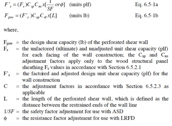
The PSW method has the following limits on its use:
- The value of Fs for the wall construction should not exceed 1,500. The wall must be fully sheathed with wood structural panels on at least one side. Unit shear values of sheathing materials may be combined.
- Full-height wall segments within a perforated shear wall should not exceed an aspect ratio of 4 (height/width) unless that portion of the wall is treated as an opening. (Some codes limit the aspect ratio to 2 or 3.5, but recent testing mentioned earlier has demonstrated otherwise.) The first wall segment on either end of a perforated shear wall must not exceed the aspect ratio limitation.
- The ends of the perforated shear wall must be restrained with hold-down devices. Hold-down forces that are transferred from the wall above are additive to the hold-down forces in the wall below. Alternatively, each wall stud may be restrained by using a strap sized to resist an uplift force equivalent to the design unit shear resistance Fs of the wall, provided that the sheathing area ratio r for the wall is not less than 0.5.
- Top plates must be continuous with a minimum connection capacity at splices with lap joints of 1,000 lbs., or as required by the design condition, whichever is greater.
- Bottom plate connections to transfer shear to the construction below (i.e., resist slip) should be designed and should result in a connection at least equivalent to one 1/2-inch anchor bolt at 6 feet on center or two 16d pneumatic nails 0.131-inch diameter at 24 inches on center for wall constructions with FsCspCns not exceeding 800 plf (ultimate capacity of interior and exterior sheathing). Such connections have been shown to provide an ultimate shear slip capacity of more than 800 plf in typical shear wall framing systems (NAHBRC, 1999). For wall constructions with ultimate shear capacities FsCspCns exceeding 800 plf, the base connection must be designed to resist the unit shear load and also provide a design uplift resistance equivalent to the design unit shear load.
- Net wind uplift forces from the roof and other tension forces as a result of structural actions above the wall are transferred through the wall by using an independent load path. Wind uplift may be resisted with the strapping option above, provided that the straps are sized to transfer the additional load.
Segmented Shear Wall Design Approach
The following equations are used to determine the adjusted and factored shear capacity of a shear wall segment:
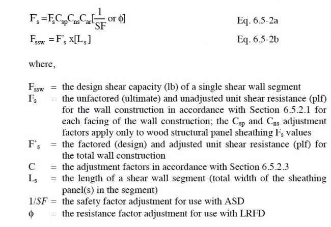
The segmented shear wall design method imposes the following limits:
- The aspect ratio of wall segments should not exceed 4 (height/width), as determined by the sheathing dimensions on the wall segment. (Absent an adjustment for the aspect ratio, current codes may restrict the segment aspect ratio to a maximum of 2 or 3.5.)
- The ends of the wall segment should be restrained. Hold-down forces that are transferred from shear wall segments in the wall above are additive to the hold-down forces in the wall below.
- Shear transfer at the base of the wall should be determined.
- Net wind uplift forces from the roof and other tension forces as a result of structural actions above are transferred through the wall by using an independent load path.
For walls with multiple shear wall segments, the design shear resistance for the individual segments may be added to determine the total design shear resistance for the segmented shear wall line. Alternatively, the combined shear capacity at given amounts of drift may be determined by using load-deformation equations.
Shear Capacity Adjustment Factors
Safety and Resistance Factors (SF and φ)
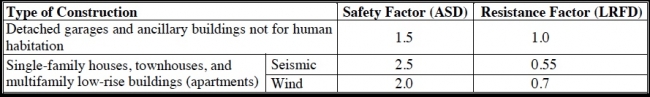
Table 5 recommends values for safety and resistance factors for shear wall design in residential construction. A safety factor of 2.5 is widely recognized for shear wall design, although the range varies substantially in current code-approved unit shear design values for wood-framed walls (i.e., the range is 2 to more than 4). In addition, a safety factor of 2 is commonly used for wind design. The 1.5 safety factor for ancillary buildings is commensurate with lower risk but may not be a recognized practice in current building codes. A safety factor of 2 has been historically applied or recommended for residential dwelling design (HUD, 1967; MPS, 1958; HUD, 1999). It is also more conservative than safety factor adjustments typically used in the design of other properties with wood members and other materials.
TABLE 5. Minimum Recommended Safety and Resistance Factors for Residential Shear Wall Design
Species Adjustment Factor (Csp)
The ultimate unit shear values for wood structural panels in Table 1 apply to lumber species with a specific gravity (density) G greater than or equal to 0.5. Table 6 presents specific gravity values for common species of lumber used for wall framing. For G less than 0.5, the following value of Csp should be used to adjust values in Table 1 only (APA, 1998):
Csp = [1−(0.5 − G)] 1.0
TABLE 6. Specific Gravity Values (Average) for Common Species of Framing Lumber

Nail Size Adjustment Factor (Cns)
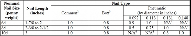
The ultimate unit shear capacities in Table 1 are based on the use of common nails. For other nail types and corresponding nominal sizes, the Cns adjustment factors in Table 7 should be used to adjust the values in Table 1. Nails should penetrate framing members a minimum of 10D, where D is the diameter of the nail.
TABLE 7. Values of Cns for Various Nail Sizes and Types
Opening Adjustment Factor (Cop)
The following equation for Cop applies only to the perforated shear wall method:
Cop = r/(3-2r)
where
r = 1/(1 + α/β) = sheathing area ratio (dimensionless)
α = ΣAo / (H x L) = ratio of area of all openings ΣAo to total wall area, H x L (dimensionless)
β = ΣLi / L = ratio of length of wall with full-height sheathing ΣLi to the total wall length L of the perforated shear wall (dimensionless)
Dead Load Adjustment Factor (Cdl)
The Cdl factor applies to the perforated shear wall method only. The presence of a dead load on a perforated shear has the effect of increasing shear capacity (Ni et al., 1998). The increase is 15 percent for a uniform dead load of 300 plf or more applied to the top of the wall framing. The dead load should be decreased by wind uplift and factored in accordance with the lateral design load combinations. The Cdl adjustment factor is determined as follows and should not exceed 1.15:

where
wD = the net uniform dead load supported at the top of the perforated shear wall (plf) with consideration of wind uplift and factoring.
Aspect Ratio Adjustment Factor (Car)
The following Car adjustment factor applies only to the segmented shear wall design method for adjusting the shear resistance of interior and exterior sheathing:
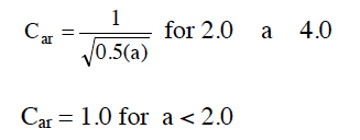
where
a is the aspect ratio (height/width) of the sheathed shear wall segment.
Overturning Restraint
Figure 3 address overturning restraint of shear walls in conceptual terms. In practice, the two generally recognized approaches to providing overturning restraint call for:
The first method applies to restrained shear wall segments in both the perforated and segmented shear wall methods. The first segment on each end of a perforated shear wall is restrained in one direction of loading. Therefore, the overturning forces on that segment are analyzed in the same manner as for a segmented shear wall. The second method listed above is a valid and conceptually realistic method of analyzing the restraint of typical residential wall constructions, but it has not yet fully matured. Further, the method’s load path (i.e., distribution of uplift forces to various connections with inelastic properties) is perhaps beyond the practical limits of a designer’s intuition. Rather than presume a methodology based on limited testing, this guide does not suggest guidelines for the second approach. However, the second method is worth consideration by a designer when attempting to understand the performance of conventional, non-engineered residential construction. Mechanics-based methods to assist in the more complicated design approach are under development.
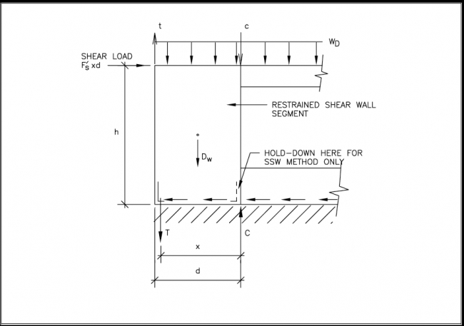
Using basic mechanics as shown in Figure 6, the following equation for the chord tension and compression forces are determined by summing moments about the bottom compression or tension side of a restrained shear wall segment:

where
T = the tension force on the hold-down device (lb)
d = the width of the restrained shear wall segment (ft); for segments greater than 4 ft in width, use d = 4 ft
x = the distance between the hold-down device and the compression edge of the restrained shear wall segment (ft); for segments greater than 4 ft in width, use x = 4 ft plus or minus the bracket offset dimension, if any
F’s = the design unit shear capacity (plf) determined
h = the height of the wall (ft)
Dw = the dead load of the shear wall segment (lb); dead load must be factored and wind uplift considered.
wD = the uniform dead load supported by the shear wall segment (plf); dead load must be factored and wind uplift considered.
t = the tension load transferred through a hold-down device, if any, restraining a wall above (lb); if there is no tension load, t = 0
c = the compression load transferred from wall segments above, if any (lb); this load may be distributed by horizontal structural elements above the wall (i.e., not a concentrated load); if there is not compression load, c = 0.
The 4-foot-width limit for d and x is imposed on the analysis of overturning forces as presented above because longer shear wall lengths mean that the contribution of the additional dead load cannot be rigidly transferred through deep bending action of the wall to have a full effect on the uplift forces occurring at the end of the segment, particularly when it is rigidly restrained from uplifting. This effect also depends on the stiffness of the construction above the wall that delivers and distributes the load at the top of the wall. The assumptions necessary to include the restraining effects of dead load is no trivial matter and, for that reason, it is common practice to not include any beneficial effect of dead load in the overturning force analysis of individual shear wall segments.
FIGURE 6.6 Evaluation of Overturning Forces on a Restrained Shear Wall Segment
For a more simplified analysis of overturning forces, the effect of dead load may be neglected and the chord forces determined as follows using the symbols defined as before:
T = C = (d/x) F’s h
Any tension or compression force transferred from shear wall overturning forces originating above the wall under consideration must be added to the result as appropriate. It is also assumed that any net wind uplift force is resisted by a separate load path (i.e., wind uplift straps are used in addition to overturning or hold-down devices).
For walls not rigidly restrained, the initiation of overturning uplift at the end stud (i.e., chord) shifts an increasing amount of the dead load supported by the wall toward the leading edge. Thus, walls restrained with more flexible hold-down devices or without such devices benefit from increased amounts of offsetting dead load, as well as from the ability of wood framing and connections to disperse some of the forces that concentrate in the region of a rigid hold-down device. However, if the bottom plate is rigidly anchored, flexibility in the hold-down device can impose undesirable cross-grain bending forces on the plate due to uplift forces transferred through the sheathing fasteners to the edge of the bottom plate. Further, the sheathing nails in the region of the bottom plate anchor experience greater load and may initiate failure of the wall through an “unzipping” effect.
The proper detailing to balance localized stiffness effects for more even force transfer is obviously a matter of designer judgment. It is mentioned here to emphasize the importance of detailing in wood-framed construction. In particular, wood framing has the innate ability to distribute loads, although weaknesses can develop from seemingly insignificant details. The concern noted above has been attributed to actual problems (i.e., bottom plate splitting) only in severe seismic events and in relatively heavily loaded shear walls. For this reason, it is now common to require larger washers on bottom plate anchor bolts, such as a 2- to 3-inch-square by 1/4-inch-thick plate washer, to prevent the development of cross-grain tension forces in bottom plates in high-hazard seismic regions. The development of high cross-grain tension stresses poses less concern when nails are used to fasten the bottom plate and are located in pairs or staggered on both sides of the wood plate. Thus, the two connection options above represent different approaches. The first, using the plate washers, maintains a rigid connection throughout the wall to prevent cross grain tension in the bottom plate. The second, using nails, is a more flexible connection that prevents concentrated cross-grain bending forces from developing. With sufficient capacity provided, the nailing approach may yield a more ductile system. Unfortunately, these intricate detailing issues are not accommodated in the single seismic response modifier used for wood-framed shear walls or the provisions of any existing code. These aspects of design are not easily “quantified” and are considered matters of qualitative engineering judgment.
Finally, it is important to recognize that the hold-down must be attached to a vertical wall framing member (i.e., a stud) that receives the wood structural panel edge nailing. If not, the hold-down will not be fully effective (i.e., the overturning forces must be delivered to the hold-down through the sheathing panel edge nailing). In addition, the method of deriving hold-down capacity ratings may vary from bracket to bracket and manufacturer to manufacturer. For some brackets, the rated capacity may be based on tests of the bracket itself that do not represent its use in an assembly (i.e., as attached to a wood member). Many hold-down brackets transfer tension through an eccentric load path that creates an end moment on the vertical framing member to which it is attached. Therefore, there may be several design considerations in specifying an appropriate hold-down device that go beyond simply selecting a device with a sufficient rated capacity from manufacturer literature. In response to these issues, some local codes may require certain reductions to or verification of rated hold-down capacities.
Shear Transfer (Sliding)
The sliding shear at the base of a shear wall is equivalent to the shear load input to the wall. To ensure that the sliding shear force transfer is balanced with the shear capacity of the wall, the connections at the base of the wall are usually designed to transfer the design unit shear capacity F’s of the shear wall. Generally, the connections used to resist sliding shear include anchor bolts (fastening to concrete) and nails (fastening to wood framing). Metal plate connectors may also be used (consult manufacturer literature). In what is a conservative decision, frictional resistance and pinching effects usually go ignored. However, if friction is considered, a friction coefficient of 0.3 may be multiplied by the dead load normal to the slippage plane to determine a nominal resistance provided by friction.
As a modification to the above rule, if the bottom plate is continuous in a perforated shear wall, the sliding shear resistance is the capacity of the perforated shear wall Fpsw. If the bottom plate is not continuous, then the sliding shear should be designed to resist the design unit shear capacity of the wall construction F’s as discussed above. Similarly, if the restrained shear wall segments in a segmented shear wall line are connected to a continuous bottom plate extending between shear wall segments, then the sliding shear can be distributed along the entire length of the bottom plate. For example, if two 4-foot shear wall segments are located in a wall 12 feet long with a continuous bottom plate, then the unit sliding shear resistance required at the bottom plate anchorage is (8 ft)(F’s)/(12 ft) or 2/3(F’s). This is similar to the mechanism by which a unit shear load is transferred from a horizontal diaphragm to the wall top plate and then into the shear wall segments through a collector (i.e., top plate).
Shear Wall Stiffness and Drift
The methods for predicting shear wall stiffness or drift in this section are based on idealized conditions representative solely of the testing conditions to which the equations are related. The conditions do not account for the many factors that may decrease the actual drift of a shear wall in its final construction. As mentioned, shear wall drift is generally overestimated in comparison with actual behavior in a completed structure. The degree of over-prediction may reach a factor of 2 at design load conditions. At capacity, the error may not be as large because some nonstructural components may be past their yield point.
The following equation for Cop applies only to the perforated shear wall method:
Cop = r/(3-2r)
where
r = 1/(1 + α/β) = sheathing area ratio (dimensionless)
α = ΣAo / (H x L) = ratio of area of all openings ΣAo to total wall area, H x L (dimensionless)
β = ΣLi / L = ratio of length of wall with full-height sheathing ΣLi to the total wall length L of the perforated shear wall (dimensionless)
Dead Load Adjustment Factor (Cdl)
The Cdl factor applies to the perforated shear wall method only. The presence of a dead load on a perforated shear has the effect of increasing shear capacity (Ni et al., 1998). The increase is 15 percent for a uniform dead load of 300 plf or more applied to the top of the wall framing. The dead load should be decreased by wind uplift and factored in accordance with the lateral design load combinations. The Cdl adjustment factor is determined as follows and should not exceed 1.15:
where
wD = the net uniform dead load supported at the top of the perforated shear wall (plf) with consideration of wind uplift and factoring.
Aspect Ratio Adjustment Factor (Car)
The following Car adjustment factor applies only to the segmented shear wall design method for adjusting the shear resistance of interior and exterior sheathing:
where
a is the aspect ratio (height/width) of the sheathed shear wall segment.
Overturning Restraint
Figure 3 address overturning restraint of shear walls in conceptual terms. In practice, the two generally recognized approaches to providing overturning restraint call for:
- the evaluation of equilibrium of forces on a restrained shear wall segment using principles of engineering mechanics; or
- the evaluation of unrestrained shear walls considering nonuniform dead load distribution at the top of the wall with restraint provided by various connections (i.e., sheathing, wall bottom plate, corner framing, etc.).
The first method applies to restrained shear wall segments in both the perforated and segmented shear wall methods. The first segment on each end of a perforated shear wall is restrained in one direction of loading. Therefore, the overturning forces on that segment are analyzed in the same manner as for a segmented shear wall. The second method listed above is a valid and conceptually realistic method of analyzing the restraint of typical residential wall constructions, but it has not yet fully matured. Further, the method’s load path (i.e., distribution of uplift forces to various connections with inelastic properties) is perhaps beyond the practical limits of a designer’s intuition. Rather than presume a methodology based on limited testing, this guide does not suggest guidelines for the second approach. However, the second method is worth consideration by a designer when attempting to understand the performance of conventional, non-engineered residential construction. Mechanics-based methods to assist in the more complicated design approach are under development.
Using basic mechanics as shown in Figure 6, the following equation for the chord tension and compression forces are determined by summing moments about the bottom compression or tension side of a restrained shear wall segment:
where
T = the tension force on the hold-down device (lb)
d = the width of the restrained shear wall segment (ft); for segments greater than 4 ft in width, use d = 4 ft
x = the distance between the hold-down device and the compression edge of the restrained shear wall segment (ft); for segments greater than 4 ft in width, use x = 4 ft plus or minus the bracket offset dimension, if any
F’s = the design unit shear capacity (plf) determined
h = the height of the wall (ft)
Dw = the dead load of the shear wall segment (lb); dead load must be factored and wind uplift considered.
wD = the uniform dead load supported by the shear wall segment (plf); dead load must be factored and wind uplift considered.
t = the tension load transferred through a hold-down device, if any, restraining a wall above (lb); if there is no tension load, t = 0
c = the compression load transferred from wall segments above, if any (lb); this load may be distributed by horizontal structural elements above the wall (i.e., not a concentrated load); if there is not compression load, c = 0.
The 4-foot-width limit for d and x is imposed on the analysis of overturning forces as presented above because longer shear wall lengths mean that the contribution of the additional dead load cannot be rigidly transferred through deep bending action of the wall to have a full effect on the uplift forces occurring at the end of the segment, particularly when it is rigidly restrained from uplifting. This effect also depends on the stiffness of the construction above the wall that delivers and distributes the load at the top of the wall. The assumptions necessary to include the restraining effects of dead load is no trivial matter and, for that reason, it is common practice to not include any beneficial effect of dead load in the overturning force analysis of individual shear wall segments.
FIGURE 6.6 Evaluation of Overturning Forces on a Restrained Shear Wall Segment
For a more simplified analysis of overturning forces, the effect of dead load may be neglected and the chord forces determined as follows using the symbols defined as before:
T = C = (d/x) F’s h
Any tension or compression force transferred from shear wall overturning forces originating above the wall under consideration must be added to the result as appropriate. It is also assumed that any net wind uplift force is resisted by a separate load path (i.e., wind uplift straps are used in addition to overturning or hold-down devices).
For walls not rigidly restrained, the initiation of overturning uplift at the end stud (i.e., chord) shifts an increasing amount of the dead load supported by the wall toward the leading edge. Thus, walls restrained with more flexible hold-down devices or without such devices benefit from increased amounts of offsetting dead load, as well as from the ability of wood framing and connections to disperse some of the forces that concentrate in the region of a rigid hold-down device. However, if the bottom plate is rigidly anchored, flexibility in the hold-down device can impose undesirable cross-grain bending forces on the plate due to uplift forces transferred through the sheathing fasteners to the edge of the bottom plate. Further, the sheathing nails in the region of the bottom plate anchor experience greater load and may initiate failure of the wall through an “unzipping” effect.
The proper detailing to balance localized stiffness effects for more even force transfer is obviously a matter of designer judgment. It is mentioned here to emphasize the importance of detailing in wood-framed construction. In particular, wood framing has the innate ability to distribute loads, although weaknesses can develop from seemingly insignificant details. The concern noted above has been attributed to actual problems (i.e., bottom plate splitting) only in severe seismic events and in relatively heavily loaded shear walls. For this reason, it is now common to require larger washers on bottom plate anchor bolts, such as a 2- to 3-inch-square by 1/4-inch-thick plate washer, to prevent the development of cross-grain tension forces in bottom plates in high-hazard seismic regions. The development of high cross-grain tension stresses poses less concern when nails are used to fasten the bottom plate and are located in pairs or staggered on both sides of the wood plate. Thus, the two connection options above represent different approaches. The first, using the plate washers, maintains a rigid connection throughout the wall to prevent cross grain tension in the bottom plate. The second, using nails, is a more flexible connection that prevents concentrated cross-grain bending forces from developing. With sufficient capacity provided, the nailing approach may yield a more ductile system. Unfortunately, these intricate detailing issues are not accommodated in the single seismic response modifier used for wood-framed shear walls or the provisions of any existing code. These aspects of design are not easily “quantified” and are considered matters of qualitative engineering judgment.
Finally, it is important to recognize that the hold-down must be attached to a vertical wall framing member (i.e., a stud) that receives the wood structural panel edge nailing. If not, the hold-down will not be fully effective (i.e., the overturning forces must be delivered to the hold-down through the sheathing panel edge nailing). In addition, the method of deriving hold-down capacity ratings may vary from bracket to bracket and manufacturer to manufacturer. For some brackets, the rated capacity may be based on tests of the bracket itself that do not represent its use in an assembly (i.e., as attached to a wood member). Many hold-down brackets transfer tension through an eccentric load path that creates an end moment on the vertical framing member to which it is attached. Therefore, there may be several design considerations in specifying an appropriate hold-down device that go beyond simply selecting a device with a sufficient rated capacity from manufacturer literature. In response to these issues, some local codes may require certain reductions to or verification of rated hold-down capacities.
Shear Transfer (Sliding)
The sliding shear at the base of a shear wall is equivalent to the shear load input to the wall. To ensure that the sliding shear force transfer is balanced with the shear capacity of the wall, the connections at the base of the wall are usually designed to transfer the design unit shear capacity F’s of the shear wall. Generally, the connections used to resist sliding shear include anchor bolts (fastening to concrete) and nails (fastening to wood framing). Metal plate connectors may also be used (consult manufacturer literature). In what is a conservative decision, frictional resistance and pinching effects usually go ignored. However, if friction is considered, a friction coefficient of 0.3 may be multiplied by the dead load normal to the slippage plane to determine a nominal resistance provided by friction.
As a modification to the above rule, if the bottom plate is continuous in a perforated shear wall, the sliding shear resistance is the capacity of the perforated shear wall Fpsw. If the bottom plate is not continuous, then the sliding shear should be designed to resist the design unit shear capacity of the wall construction F’s as discussed above. Similarly, if the restrained shear wall segments in a segmented shear wall line are connected to a continuous bottom plate extending between shear wall segments, then the sliding shear can be distributed along the entire length of the bottom plate. For example, if two 4-foot shear wall segments are located in a wall 12 feet long with a continuous bottom plate, then the unit sliding shear resistance required at the bottom plate anchorage is (8 ft)(F’s)/(12 ft) or 2/3(F’s). This is similar to the mechanism by which a unit shear load is transferred from a horizontal diaphragm to the wall top plate and then into the shear wall segments through a collector (i.e., top plate).
Shear Wall Stiffness and Drift
The methods for predicting shear wall stiffness or drift in this section are based on idealized conditions representative solely of the testing conditions to which the equations are related. The conditions do not account for the many factors that may decrease the actual drift of a shear wall in its final construction. As mentioned, shear wall drift is generally overestimated in comparison with actual behavior in a completed structure. The degree of over-prediction may reach a factor of 2 at design load conditions. At capacity, the error may not be as large because some nonstructural components may be past their yield point.
At the same time, drift analysis may not consider the factors that also increase drift, such as deformation characteristics of the hold-down hardware (for hardware that is less stiff than that typically used in testing), lumber shrinkage (i.e., causing time-delayed slack in joints), lumber compression under heavy shear wall compression chord load, and construction tolerances. Therefore, the results of a drift analysis should be considered as a guide to engineering judgment, not an exact prediction of drift.
The load-drift equations in this section may be solved to yield shear wall resistance for a given amount of shear wall drift. In this manner, a series of shear wall segments or even perforated shear walls embedded within a given wall line may be combined to determine an overall load-drift relationship for the entire wall line. The load-drift relationships are based on the nonlinear behavior of wood-framed shear walls and provide a reasonably accurate means of determining the behavior of walls of various configurations. The relationship may also be used for determining the relative stiffness of shear wall lines in conjunction with the relative stiffness method of distributing lateral building loads and for considering torsional behavior of a building with a nonsymmetrical shear wall layout in stiffness and in geometry. The approach is fairly straightforward and is left to the reader for experimentation.
Perforated Shear Wall Load-Drift Relationship
The load-drift equation below is based on several perforated shear wall tests already discussed in this article. It provides a nonlinear load-drift relationship up to the ultimate capacity of the perforated shear wall. When considering shear wall load-drift behavior in an actual building, the reader is reminded of the aforementioned accuracy issues; however, accuracy relative to the test data is reasonable (i.e., plus or minus 1/2-inch at capacity).
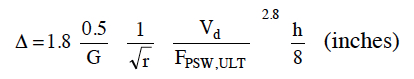
where
Δ = the shear wall drift (in) at shear load demand, Vd (lb)
G = the specific gravity of framing lumber (see Table 6)
R = the sheathing area ratio
Vd = the shear load demand (lb) on the perforated shear wall; the value of Vd is set at any unit shear demand less than or equal to Fpsw,ult while the value of Vd should be set to the design shear load when checking drift at design load conditions
Fpsw,ult = the unfactored (ultimate) shear capacity (lb) for the perforated shear wall (i.e., Fpsw X SF or Fpsw/φ for ASD and LRFD, respectively)
h = the height of wall (ft)
Segmented Shear Wall Load-Drift Relationship
APA Semi-Empirical Load-Drift Equation
Several codes and industry design guidelines specify a deflection equation for shear walls that includes a multipart estimate of various factors’ contribution to shear wall deflection (ICBO, 1997; ICC, 1999, APA, 1997). The approach relies on a mix of mechanics-based principles and empirical modifications. The principles and modifications are not repeated here because the APA method of drift prediction is considered no more reliable than that presented next. In addition, the equation is complex relative to the ability to predict drift accurately. It also requires adjustment factors, such as a nail-slip factor, that can only be determined by testing.
Empirical, Nonlinear Load-Drift Equation
Drift in a wood structural panel shear wall segment may be approximated in accordance with the following equation:
where
Δ = the shear wall drift (in) at load Vd (lb)
G = the specific gravity of framing lumber
a = the shear wall segment aspect ratio (height/width) for aspect ratios from 4 to 1; a value of 1 shall be used for shear wall segments with width (length) greater than height
Vd = the shear load demand (lb) on the wall; the value of Vd is set at any unit shear demand less than or equal to Fssw,ult while the value of Vd should be set to the design load when checking drift at design load conditions
Fssw,ult = the unfactored (ultimate) shear capacity (lb) of the shear wall segment (i.e., Fssw x SF or Fssw/φ for ASD and LRFD, respectively)
h = the height of wall (ft)
The above equation is based on several tests of shear wall segments with aspect ratios ranging from 4:1 to 1:5.
Portal Frames
In situations with little space to include sufficient shear walls to meet required loading conditions, the designer must turn to alternatives. An example is a garage opening supporting a two-story home on a narrow lot such that other wall openings for windows and an entrance door leaves little room for shear walls. One option is to consider torsion and the distribution of lateral loads in accordance with the relative stiffness method. Another possibility is the use of a portal frame.
Portal frames may be simple, specialized framing details that can be assembled on site. They use fastening details, metal connector hardware, and sheathing to form a wooden moment frame and, in many cases, perform adequately. Various configurations of portal frames have undergone testing and provide data and details on which the designer can base a design (NAHBRC, 1998; APA, 1994). The ultimate shear capacity of portal frames ranges from 2,400 to more than 6,000 pounds depending on the complexity and strength of the construction details. A simple detail involves extending a garage header so that it is end-nailed to a full-height corner stud, strapping the header to the jamb studs at the portal opening, attaching sheathing with a standard nailing schedule, and anchoring the portal frame with typical perforated shear wall requirements. The system has an ultimate shear capacity of about 3,400 pounds that, with a safety factor of 2 to 2.5, provides a simple solution for many portal frame applications for residential construction in high-hazard seismic or wind regions. Several manufacturers offer pre-engineered portal frame and shear wall elements that can be ordered to custom requirements or standard conditions.
Diaphragm Design
Diaphragm Design Values
Depending on the location and number of supporting shear wall lines, the shear and moments on a diaphragm are determined by using the analogy of a simply supported or continuous span beam. The designer uses the shear load on the diaphragm per unit width of the diaphragm (i.e., floor or roof) to select a combination of sheathing and fastening from a table of allowable horizontal diaphragm unit shear values found in U.S. building codes. Similar to those for shear walls, unit shear values for diaphragms vary according to sheathing thickness and nailing schedules, among other factors. Table 8 presents several of the more common floor and roof constructions used in residential construction as well as their allowable diaphragm resistance values. The values include a safety factor for ASD and therefore require no additional factoring. The aspect ratio of a diaphragm should be no greater than 4 (length/width) in accordance with current building code limits. In addition, the sheathing attachment in floor diaphragms is often supplemented with glue or construction adhesive. A similar increase to the unit shear capacity of floor diaphragms can be expected, not to mention increased stiffness when the floor sheathing is glued and nailed.
TABLE 8. Horizontal Diaphragm ASD Shear Values (plf) for Unblocked Roof and Floor Construction Using Douglas Fir or Southern Pine Framing

Diaphragm Design
As noted, diaphragms are designed in accordance with simple beam equations. To determine the shear load on a simply supported diaphragm (i.e., diaphragm supported by shear walls at each side), the designer uses the following equation to calculate the unit shear force to be resisted by the diaphragm sheathing:

where
Vmax = the maximum shear load on the diaphragm (plf)
w = the tributary uniform load (plf) applied to the diaphragm resulting from seismic or wind loading
l = the length of the diaphragm perpendicular to the direction of the load
(ft) vmax = the unit shear across the diaphragm in the direction of the load (plf)
d = the depth or width of the diaphragm in the direction of the load (ft)
The following equations are used to determine the theoretical chord tension and compression forces on a simply supported diaphragm as described above:
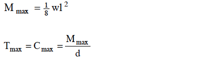
where
Mmax = the bending moment on the diaphragm (ft-lb)
w = the tributary uniform load (plf) applied to the diaphragm resulting from seismic or wind loading
l = the length of the diaphragm perpendicular to the direction of the load
(ft)
Tmax = the maximum chord tension force (lb)
Cmax = the maximum chord compression force (lb)
d = the depth or width of the diaphragm in the direction of the load (ft)
If the diaphragm is not simply supported at its ends, the designer uses appropriate beam equations (see Appendix A) in a manner similar to that above to determine the shear and moment on the diaphragm. The calculations to determine the unit shear in the diaphragm and the tension and compression in the chords are also similar to those given above. It should be noted that the maximum chord forces occur at the location of the maximum moment. For a simply supported diaphragm, the maximum chord forces occur at mid-span between the perimeter shear walls. Thus, chord requirements may vary depending on location and magnitude of the bending moment on the diaphragm. Similarly, shear forces on a simply supported diaphragm are highest near the perimeter shear walls (i.e., reactions). Therefore, nailing requirements for diaphragms may be adjusted depending on the variation of the shear force in interior regions of the diaphragm. Generally, these variations are not critical in small residential structures such that fastening schedules can remain constant throughout the entire diaphragm. If there are openings in the horizontal diaphragm, the width of the opening dimension is usually discounted from the width d of the diaphragm when determining the unit shear load on the diaphragm.
Shear Transfer (Sliding)
The shear forces in the diaphragm must be adequately transferred to the supporting shear walls. For typical residential roof diaphragms, conventional roof framing connections are often sufficient to transfer the small sliding shear forces to the shear walls (unless heavy roof coverings are used in high-hazard seismic areas or steep roof slopes are used in high-hazard wind regions). The transfer of shear forces from floor diaphragms to shear walls may also be handled by conventional nailed connections between the floor boundary member (i.e., a band joist or end joist that is attached to the floor diaphragm sheathing) and the wall framing below. In heavily loaded conditions, metal shear plates may supplement the connections. The simple rule to follow for these connections is that the shear force in from the diaphragm must equal the shear force out to the supporting wall. Floors supported on a foundation wall are usually connected to a wood sill plate bolted to the foundation wall; however, the floor joist and/or the band joist may be directly connected to the foundation wall.
Diaphragm Stiffness
Diaphragm stiffness may be calculated by using semi-empirical methods based on principles of mechanics. The equations are found in most modern building codes and industry guidelines (APA, 1997; ICBO, 1997; ICC, 1999). For typical residential construction, however, the calculation of diaphragm deflection is almost never necessary and rarely performed. Therefore, the equations and their empirical adjustment factors are not repeated here. Nonetheless, the designer who attempts diaphragm deflection or stiffness calculations is cautioned regarding the same accuracy concerns mentioned for shear wall drift calculations. The stiffness of floor and roof diaphragms is highly dependent on the final construction, including interior finishes.

Structural Design Concepts for the Home Inspector
Structural Design Loads for the Home Inspector
Structural Design of Foundations for the Home Inspector
Structural Design Loads for the Home Inspector
Structural Design of Foundations for the Home Inspector