OBSERVATION #1
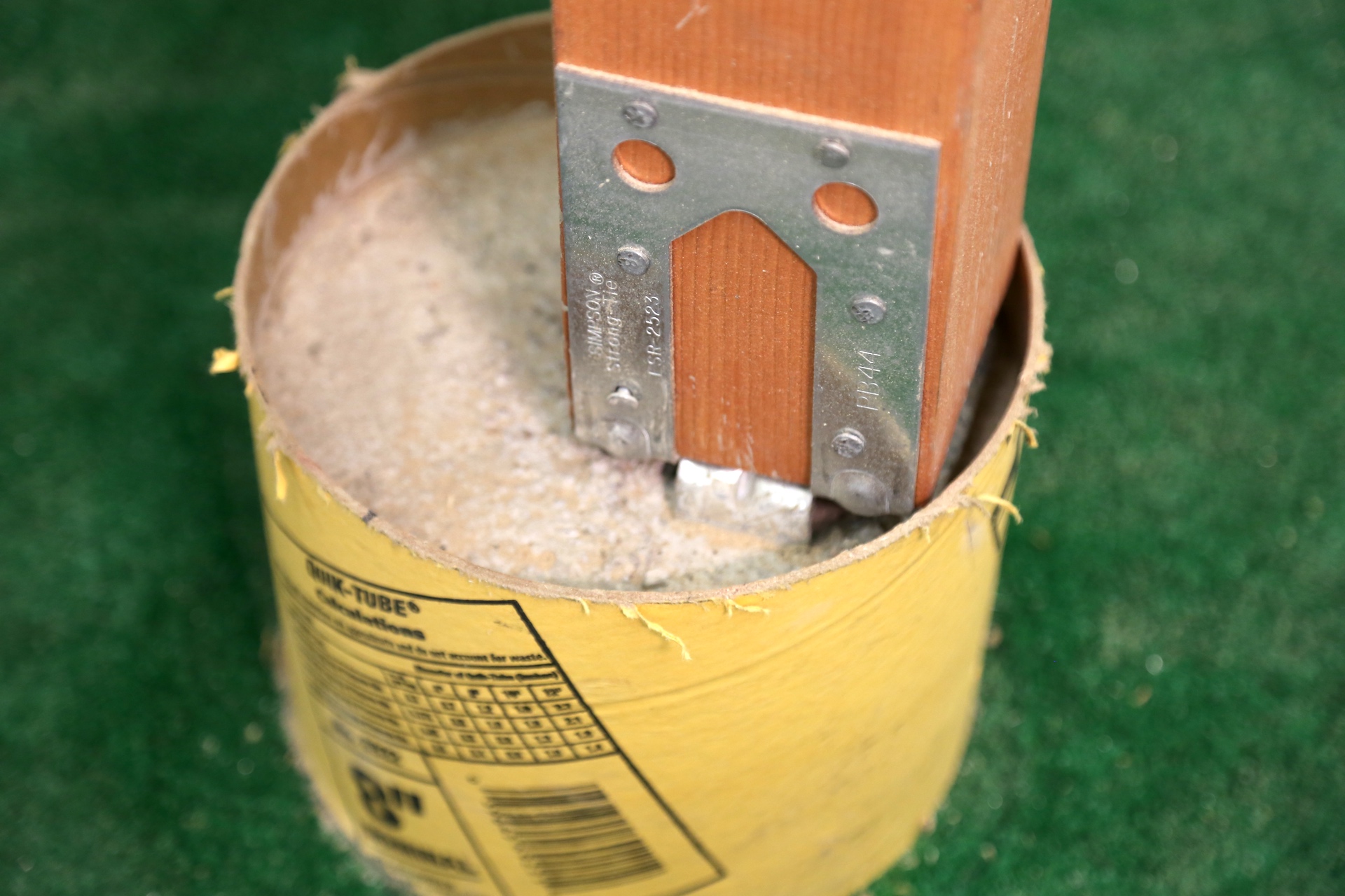
The deck posts are off-center in relation to their footings.
OBSERVATION #2
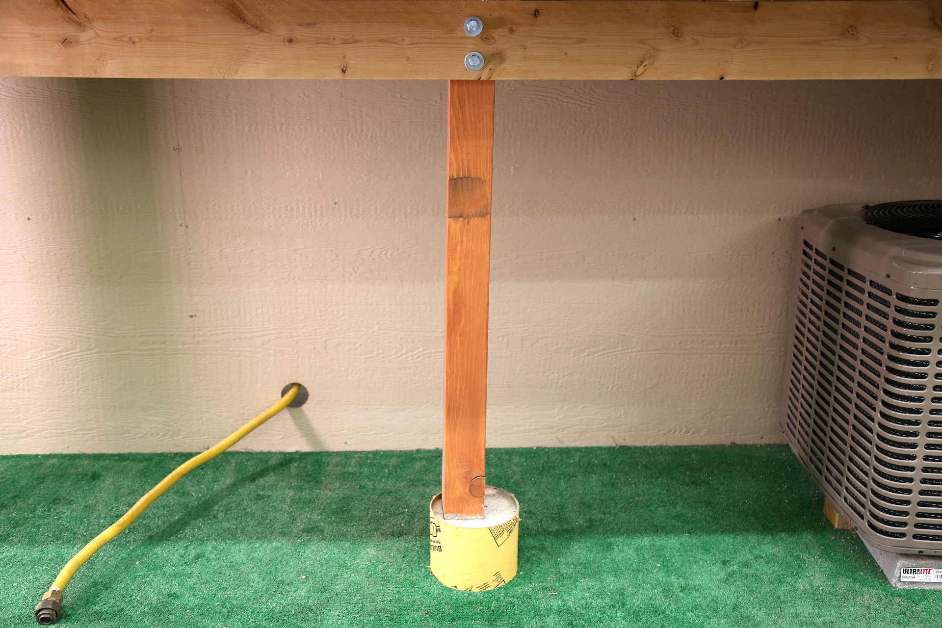
The posts are out of plumb.
OBSERVATION #3
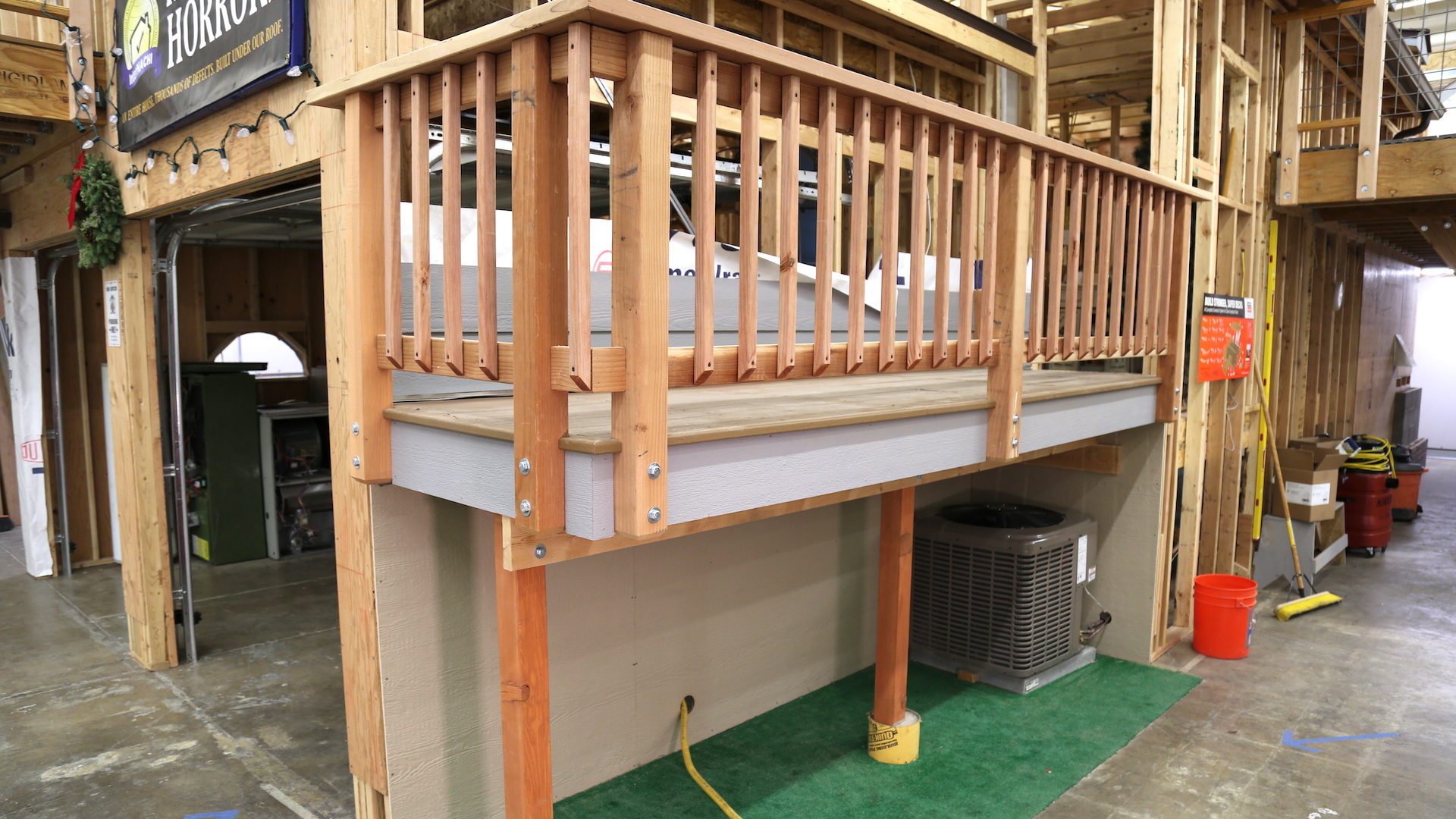
In all but the lowest of decks, deck posts should be at least 6x6, and be no higher than 12 feet; 14 feet is acceptable if cross-bracing is used.
OBSERVATION #4
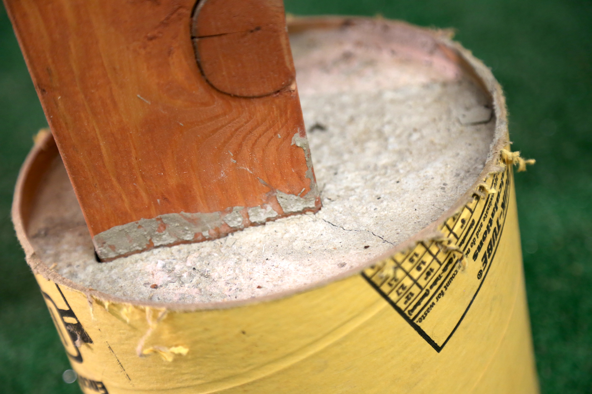
A post bottom is embedded into concrete.
The one post is not securely attached to its footing. Posts should be connected to their footings so that the posts don't lift or slip off.
In accordance with IRC 2015 507.8.1, deck posts can bear on footings in a few different ways, including having the post bear on concrete stems, bear on a typical footing above or below grade, and bear on a concrete footing and encased in concrete.
OBSERVATION #5
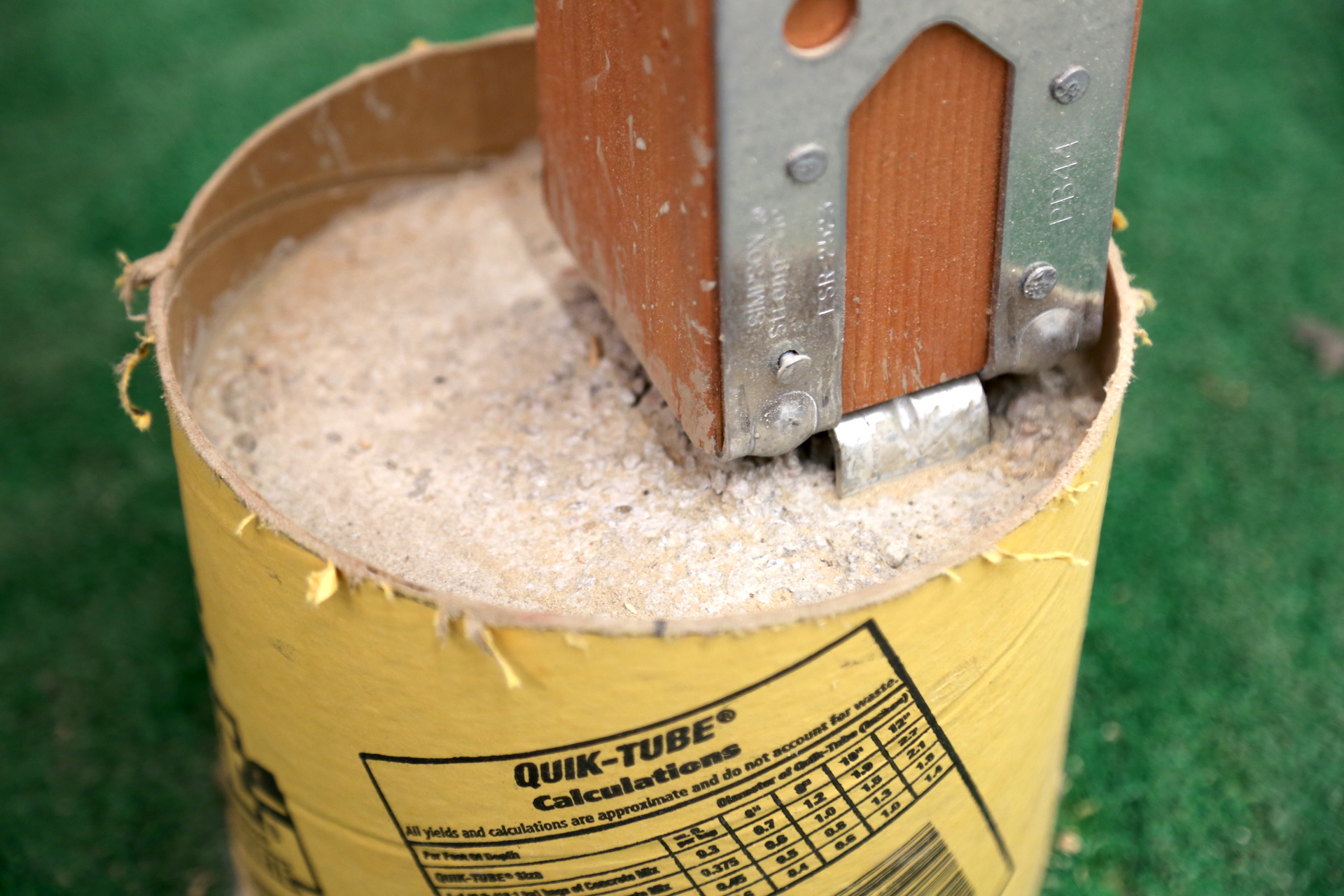
The footing tube will hold water, which may cause wood decay.
OBSERVATION #6
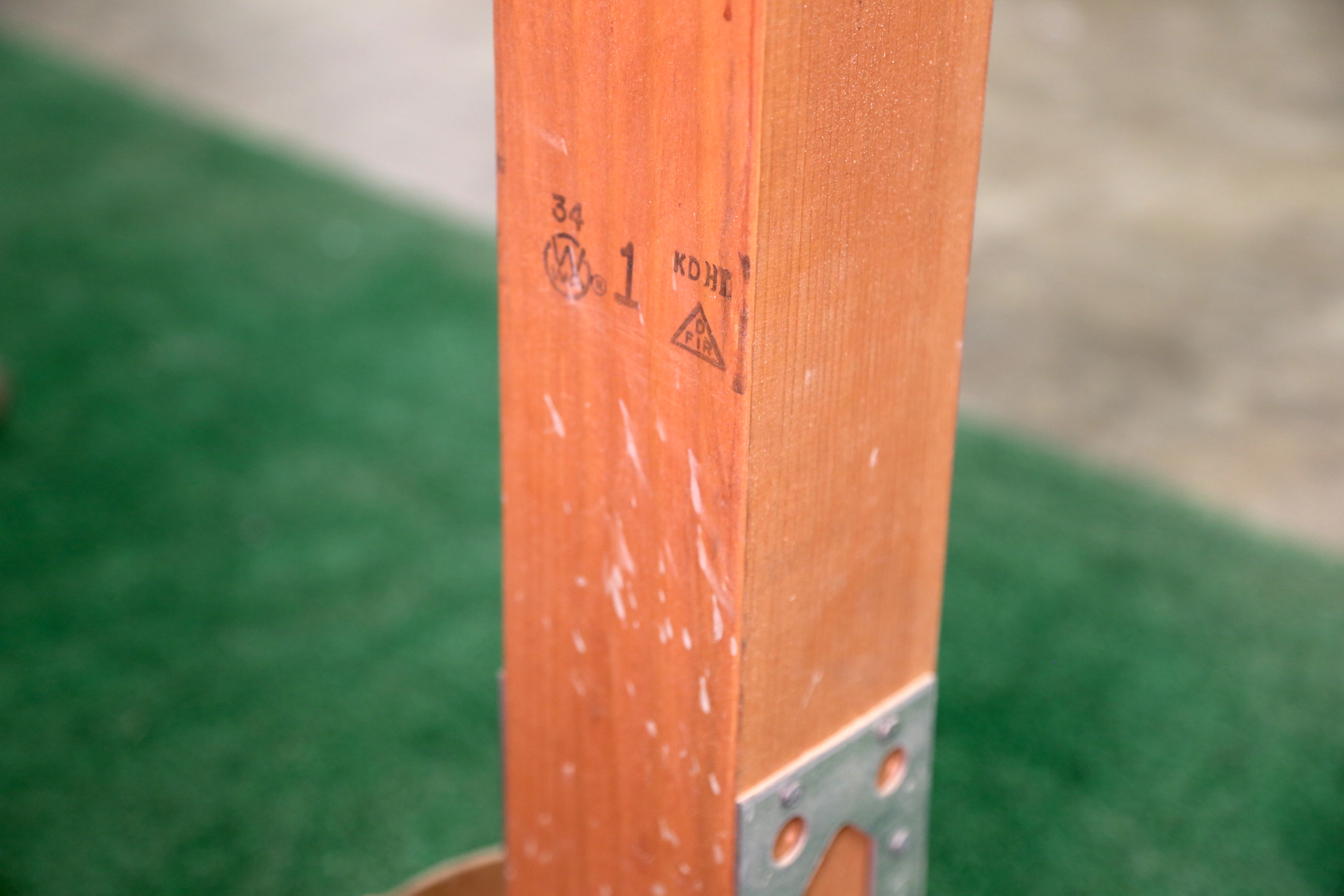
The posts are not of decay-resistant wood. See the stamp on the back of a post indicating that it is Douglas Fir.
Posts in contact with soil should be pressure-treated and oriented so the cut end is above grade.
OBSERVATION #7
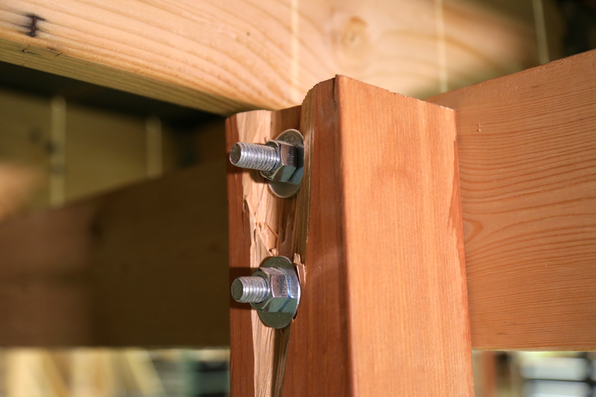
One post is damaged where the through-bolts penetrate.
OBSERVATION #8
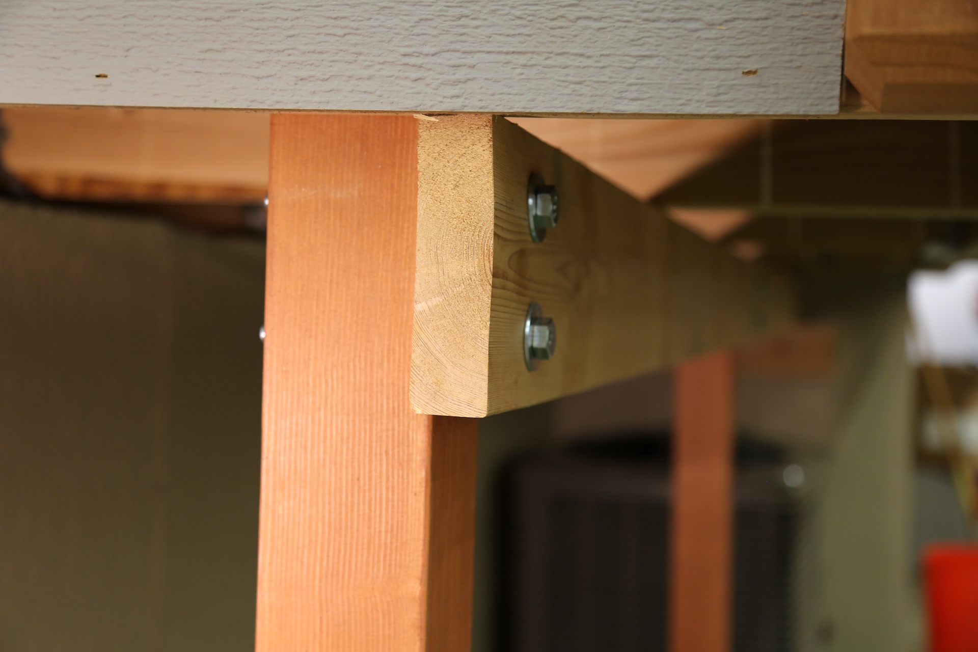
The main deck beam is undersized. It's made of only a single board.
The deck beam size depends upon the wood species and the deck joist span. The minimum size of a deck beam should be made of two 2x6 boards, and the deck beam depth should be greater than or equal to the depth of the joists.
Deck beams are permitted to cantilever at each end up to 1/4 of the actual beam span.
OBSERVATION #9
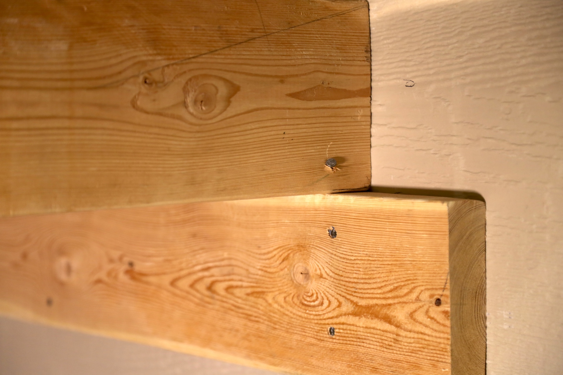
The deck beam is inadequately supported at the house wall.
OBSERVATION #10
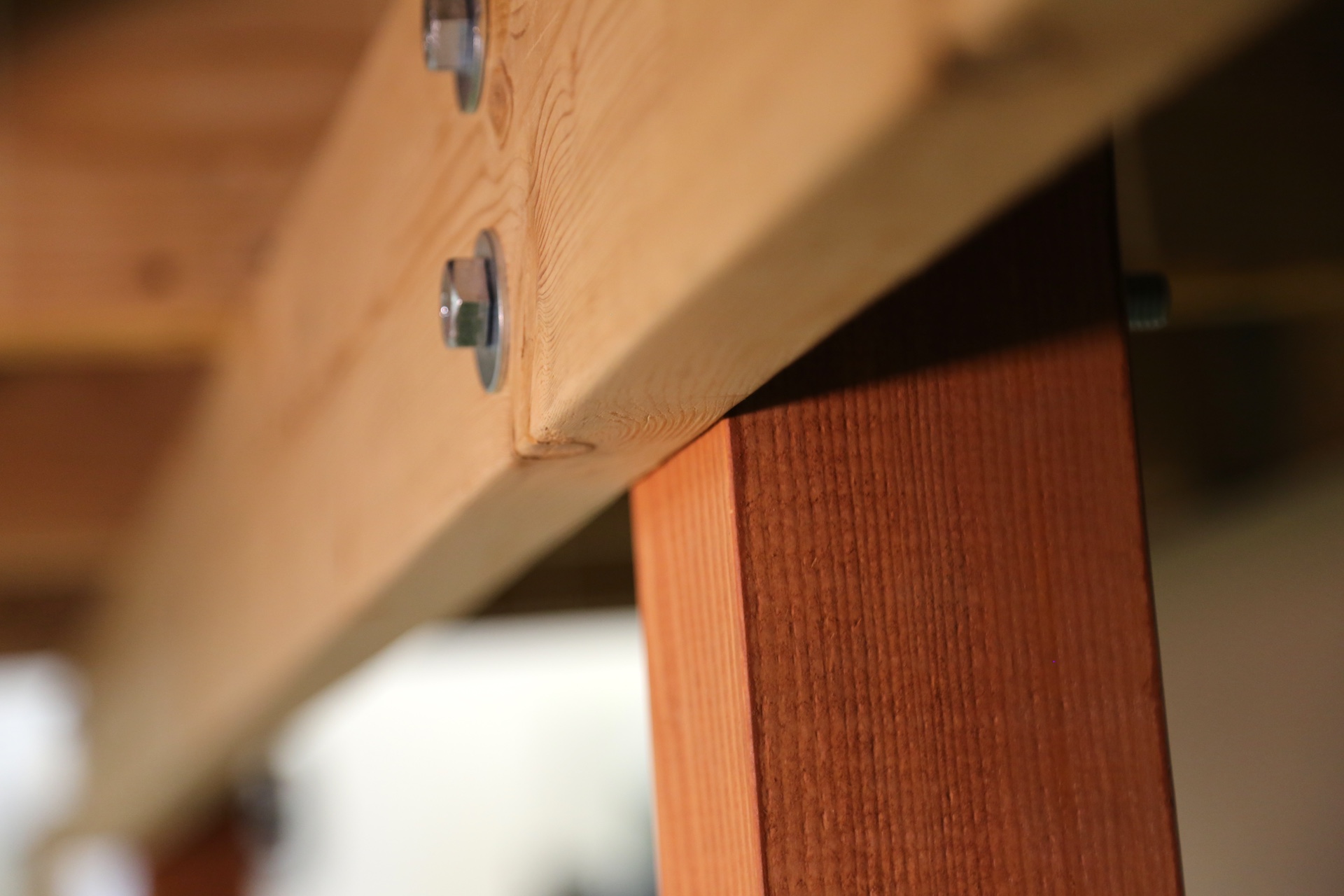
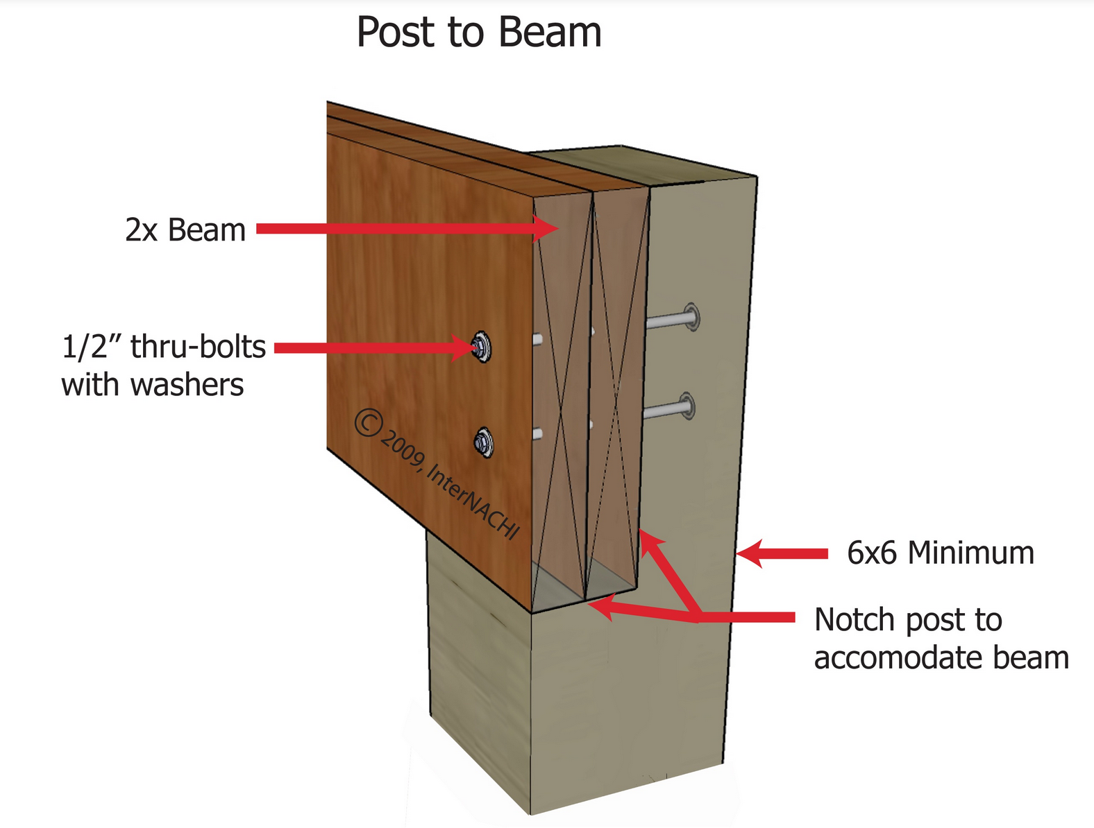
The deck beam has no direct bearing on the posts. A beam should not rely on the shear strength of lag bolts or screws. A deck beam should bear directly on the deck post that uses:
- a notched post;
- an approved post cap connector; or
- other equivalent means that resists lateral displacement.
All bolts should have washers under the head and nut.
OBSERVATION #11
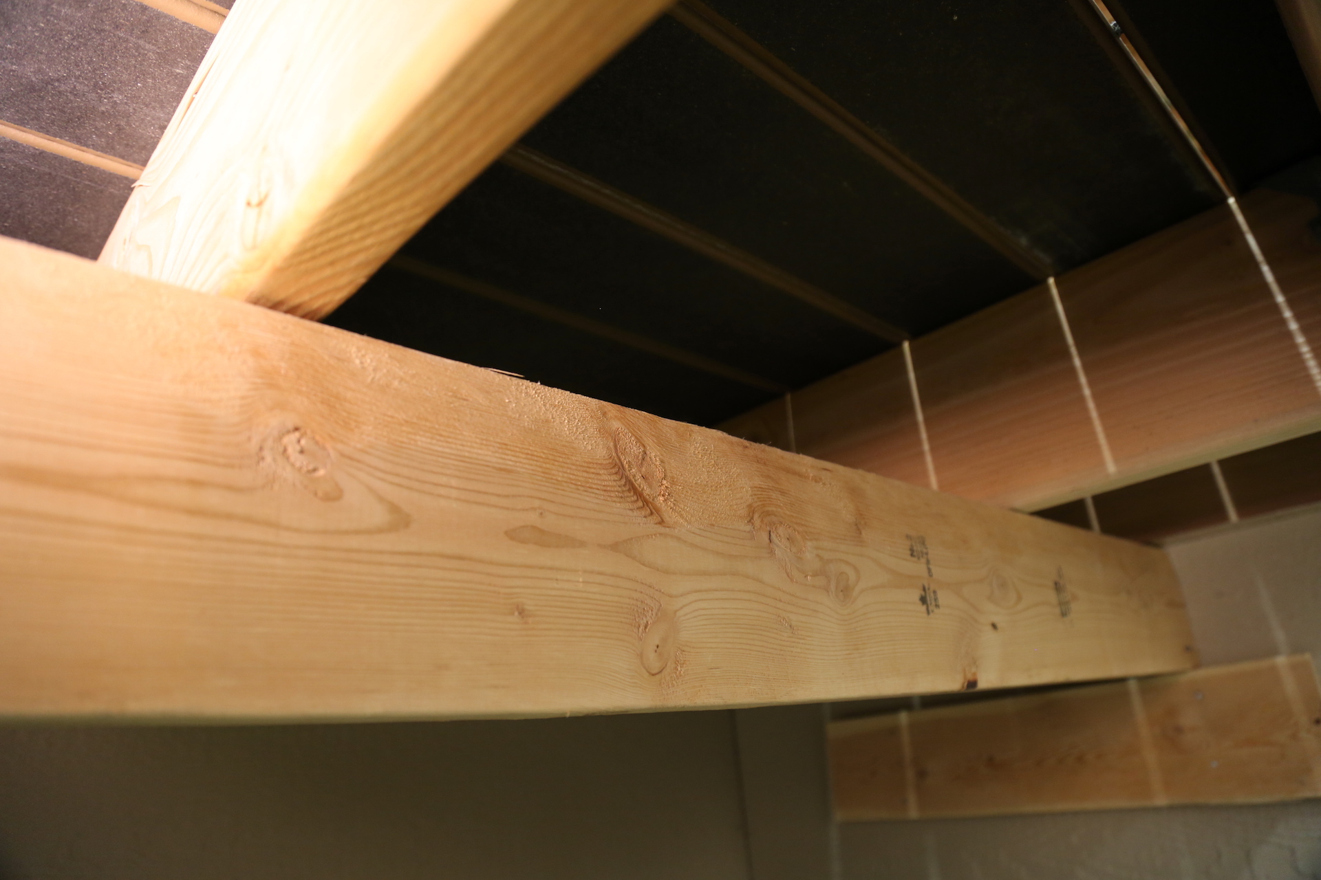
Solid blocking between the joists and above the deck beam is recommended.
OBSERVATION #12

Not all of the joists are nailed to the deck beam. There should be a connector at each joist and beam connection point to create a continuous load path. Joists that bear on a beam must be connected to the beam to resist lateral displacement.
A continuous load path is a method of construction that uses metal connectors to create a series of solid connections within the structure of the deck. This path transfers the load or weight of the deck through its frame and into the ground and adjacent support structure (typically the house). If the deck is built with a continuous load path, it will be better equipped to resist the forces that can weaken the deck.
OBSERVATION #13

Ledger Attachment
The most common cause of deck collapse is when a ledger pulls away from the band joists of homes and buildings.
The two most common ways to correctly attach a ledger to a structure are with lag screws or through-bolts. Where supported by attachment to an exterior wall, decks should be positively anchored to the house. And that anchored attachment can not be accomplished by the use of toenails or nails subject to withdrawal.
The bolts at the ledger board are inadequately sized.
OBSERVATION #14
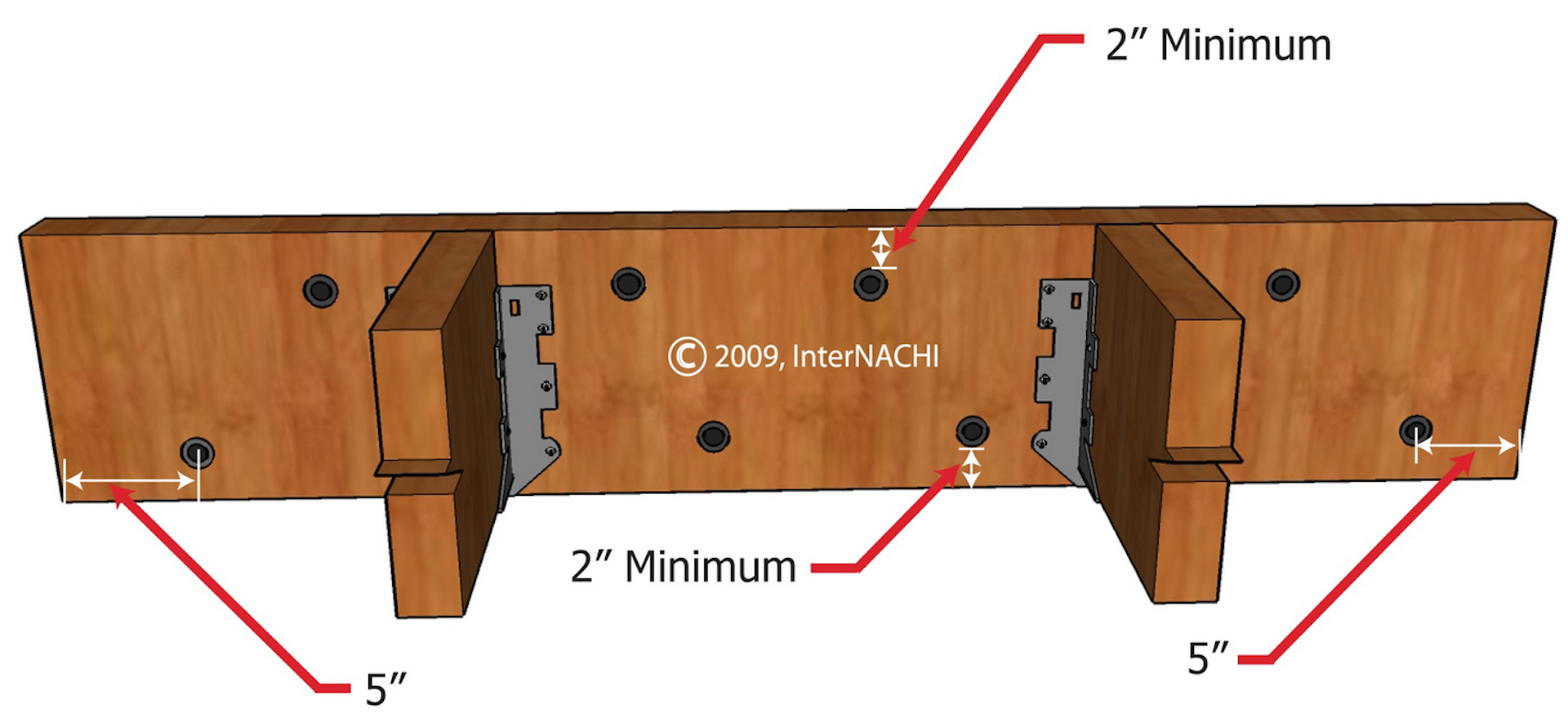
The ledger bolts are not properly spaced.
- joist length;
- type of fastener;
- diameter of fastener;
- sheathing thickness;
- use of stacked washers;
- type of wood species;
- moisture content;
- band joist integrity; and
- deck loads...
...and so is beyond the scope of a home inspection. However, the spacing of ledger fasteners required is primarily determined by the length of the joists.
InterNACHI's ledger fastener spacing formula provides inspectors with this rule of thumb:
On-center spacing of ledger fasteners in inches = 100 ÷ joist length in feet.
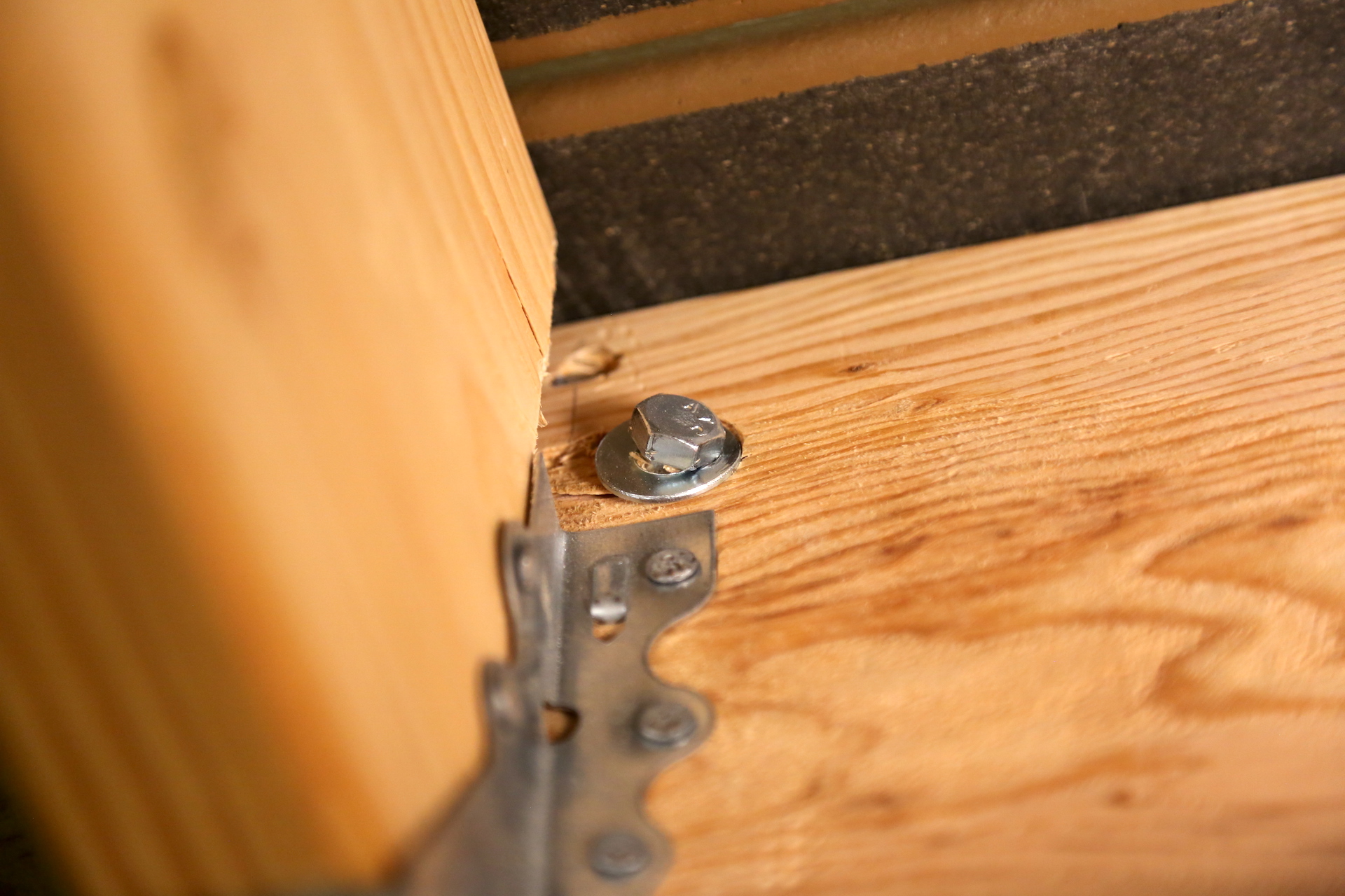
The ledger bolt is not installed perpendicular to the ledger board. It's installed at an angle.
OBSERVATION #15
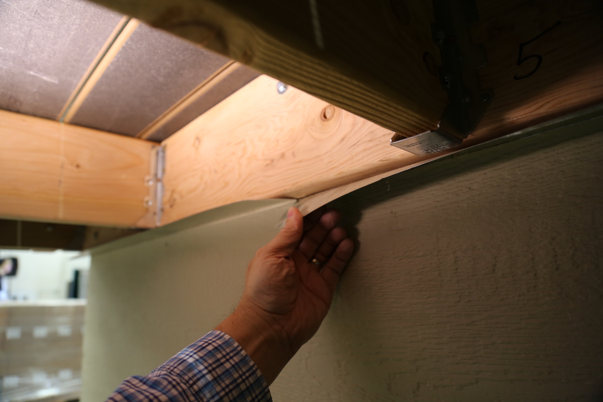
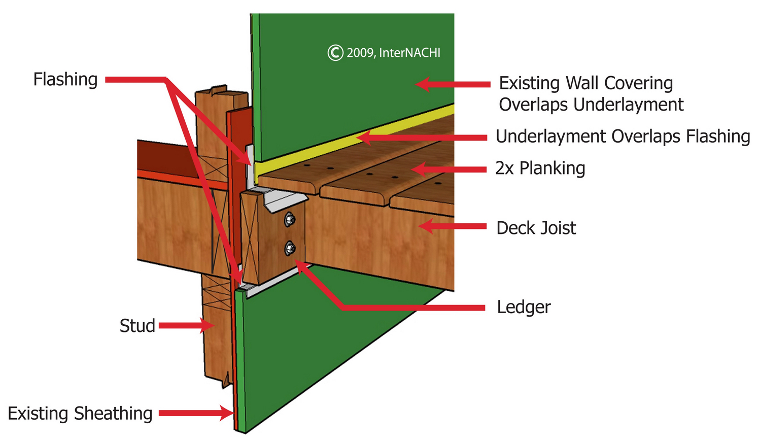
The flashing material at the top and bottom of the ledger board is improperly installed. The ledger board flashing should z-type flashing and not a simple angle flashing.
OBSERVATION #16

The deck floor structure is cantilevered past the deck beam. Joists should be cantilevered no more than one-quarter of the joist length and three times the joist width (nominal depth). Both conditions must be true.
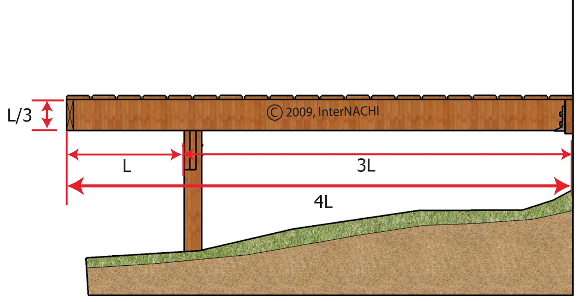
OBSERVATION #17

There are open gaps of space between the bottom of joists and the joist hanger pocket.
OBSERVATION #18
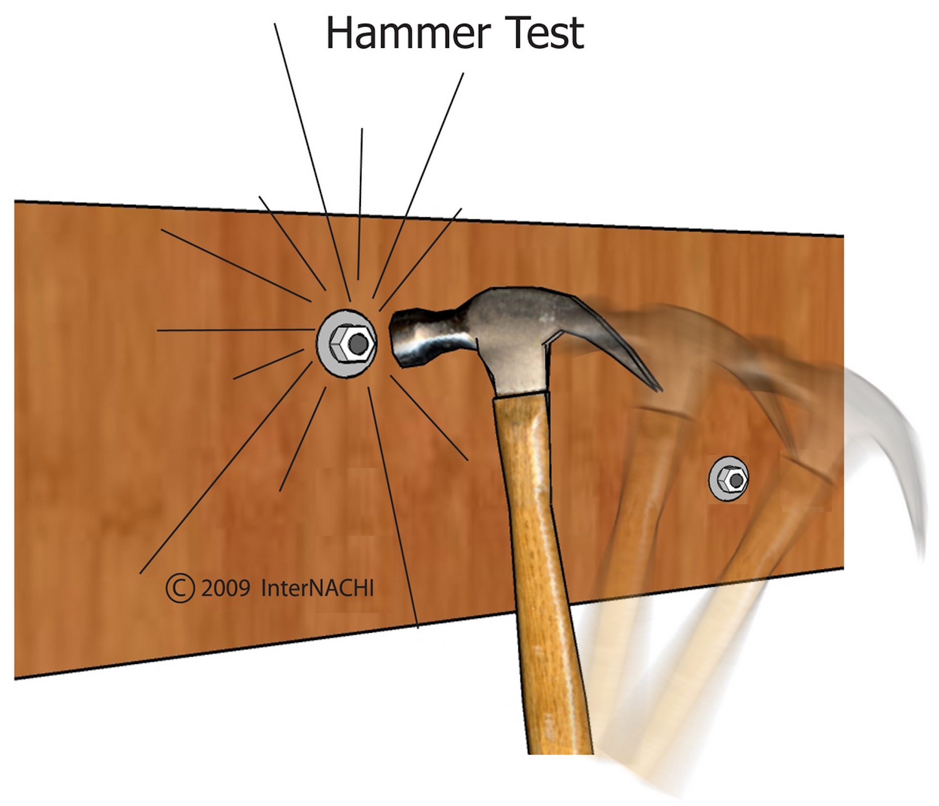
If it is not possible to reach both sides of a bolt, it may be struck with a hammer. The ring will sound hollow with vibration if the fastener is loose. The ring will sound solid if the connection is tight. The hammer test is subjective, so the inspector should hammer-test bolts that can be confirmed as tight or loose, and compare the sounds of the rings to develop a control.
OBSERVATION #19
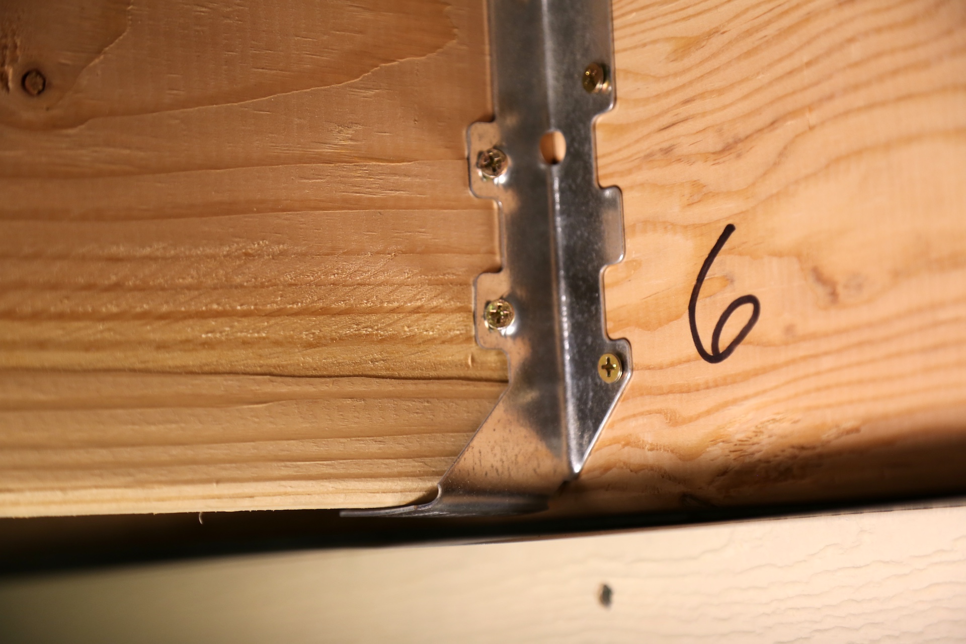
The wrong type of fasteners are installed at the joist hangers.
All screws, bolts and nails should be hot-dipped galvanized, stainless steel, silicon bronze, copper, zinc-coated or corrosion-resistant. Metal connectors and fasteners can corrode over time, especially if a product with insufficient corrosion-resistance was originally installed. Corrosion of a fastener affects both the fastener and the wood. As the fastener corrodes, it causes the wood around it to deteriorate. As the fastener becomes smaller, the void around it becomes larger. Inspectors normally do not remove fasteners to check their quality or size, but if the inspector removes a fastener, he should make sure that removal doesn't result in a safety issue. Fasteners removed should be from areas that have the greatest exposure to weather. Some inspectors carry new fasteners to replace ones they remove at the inspection.
OBSERVATION #20

There are joist hangers installed upside down.
Simpson Strong Tie recommends joist hangers to be installed at the ledger board and angle brackets at the outer rim joist.
OBSERVATION #21

The deck boards span too great of a distance between the joists. This type of decking requires floor joists to be installed 16 inches on center.
OBSERVATION #22
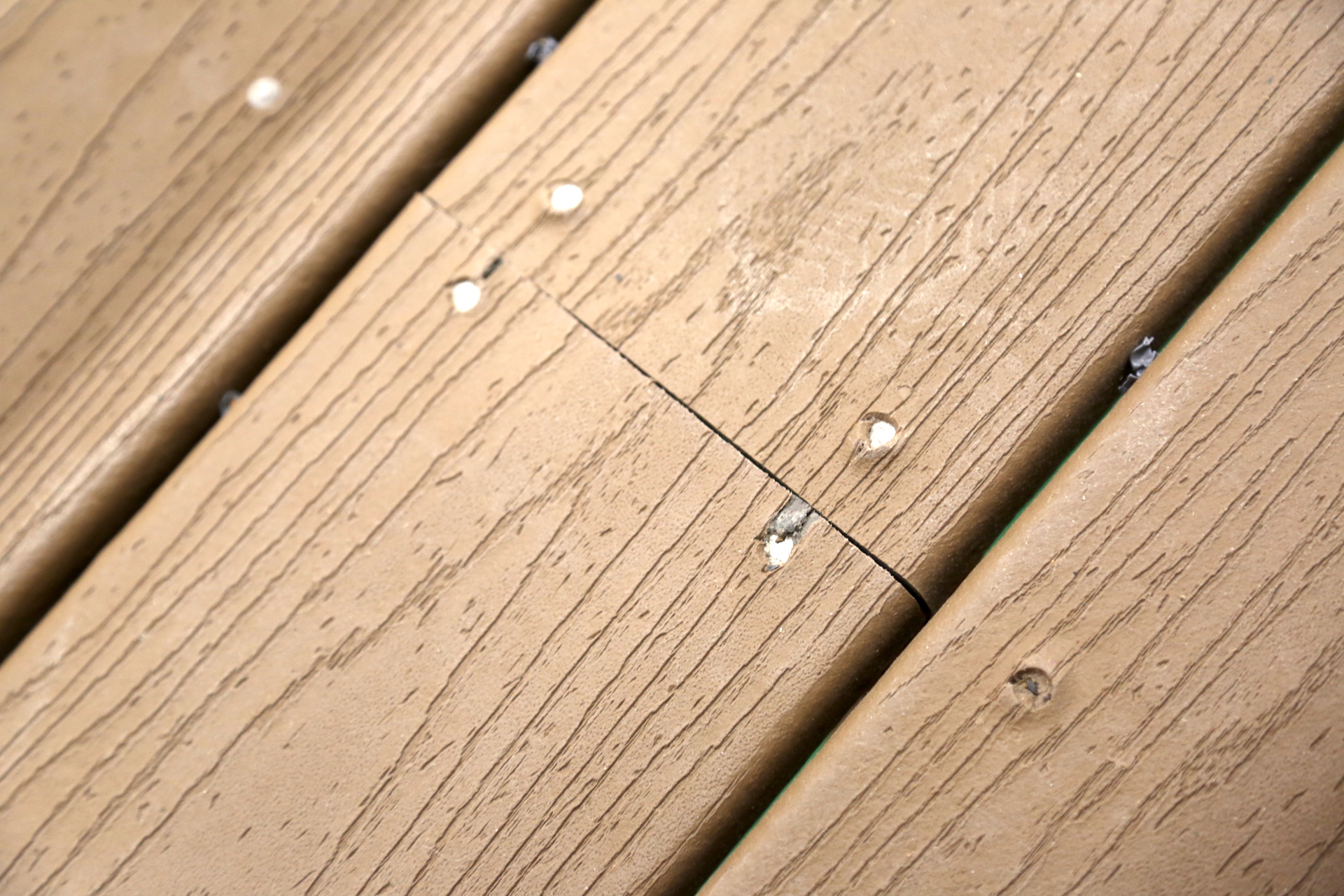
The deck floor boards should be installed with screws, not nails.
OBSERVATION #23
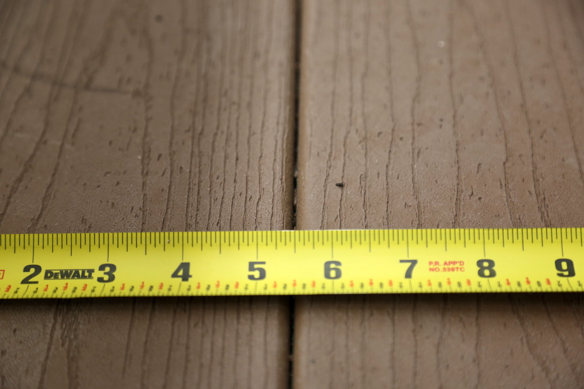
There should be a small open space between the deck floor boards to provide for expansion, contraction, and water drainage.
OBSERVATION #24
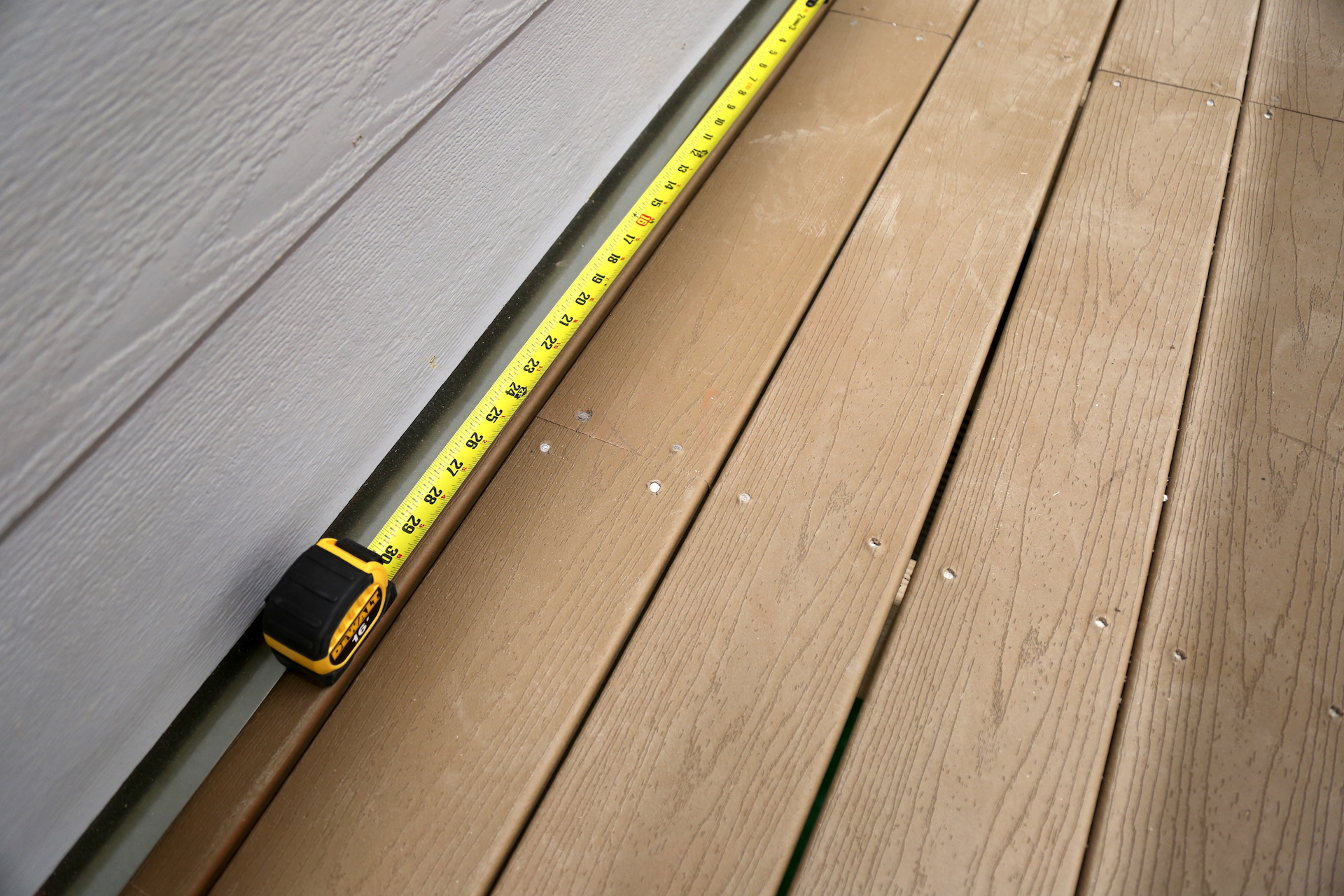
There is a deck board that spans only one joist bay. Each segment of deck boards should bear on a minimum of four joists.
OBSERVATION #25
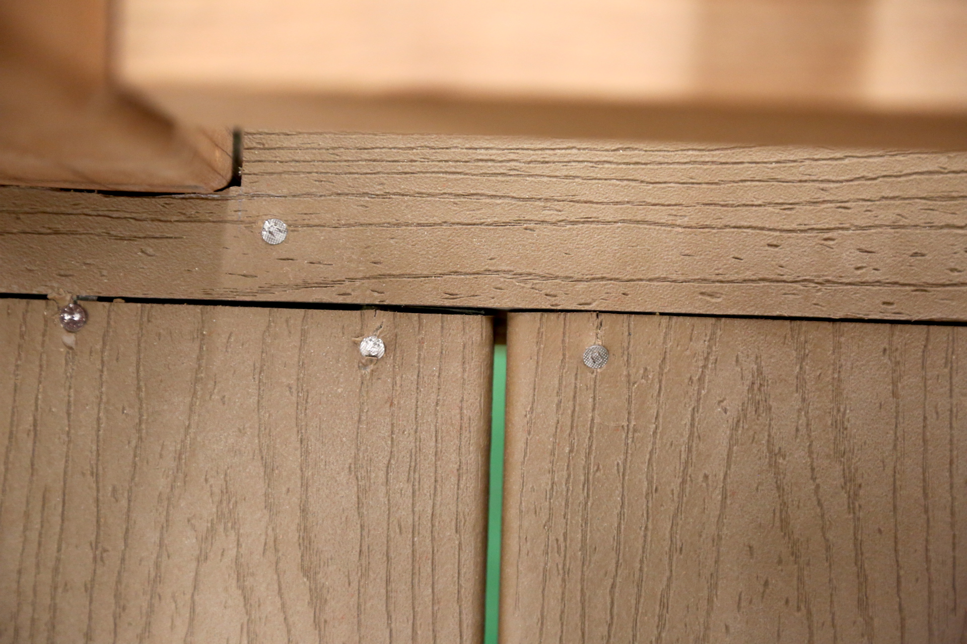
There are deck boards with inadequate bearing on their ends.
OBSERVATION #26
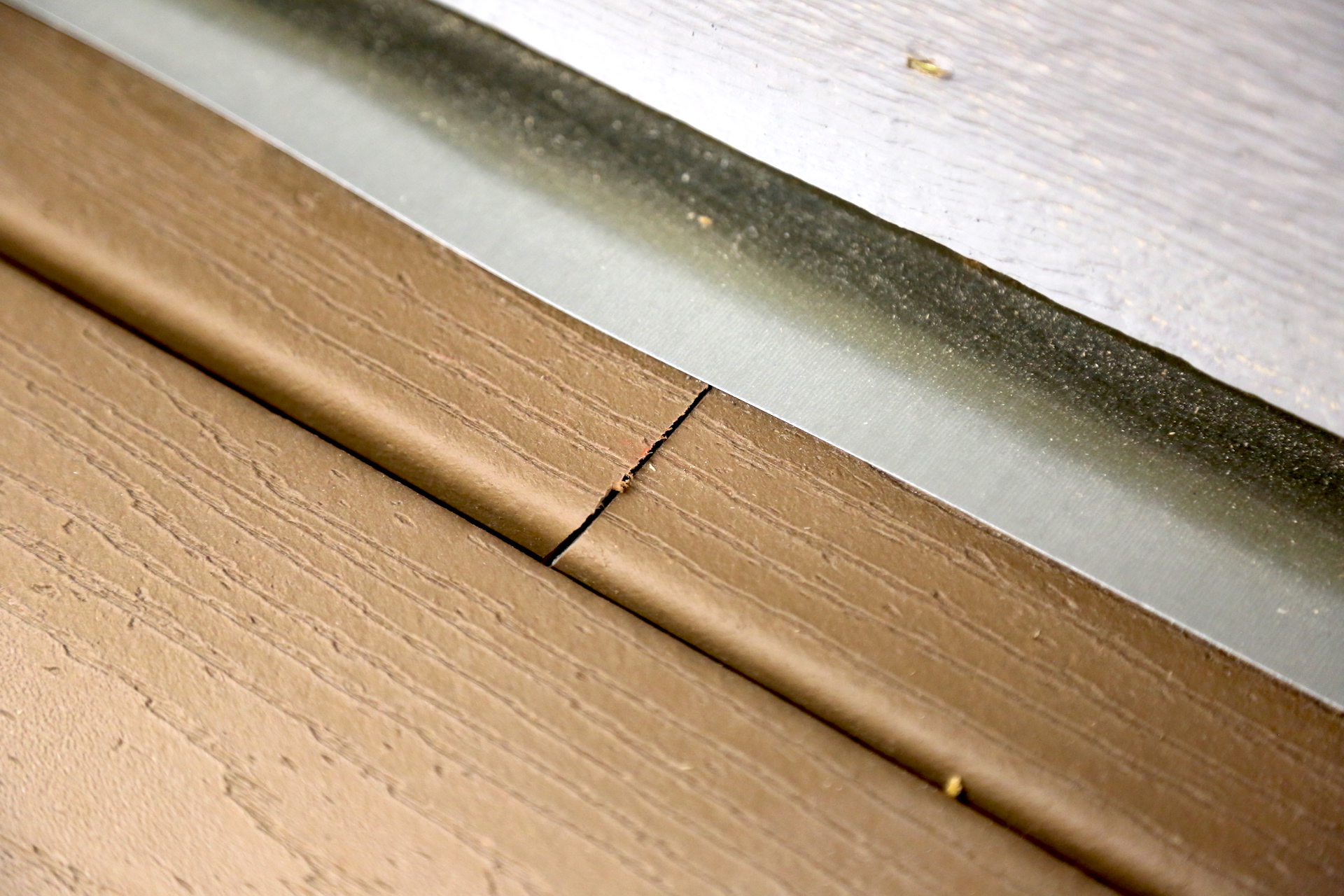
Some deck boards do not end on top of a joist.
OBSERVATION #27
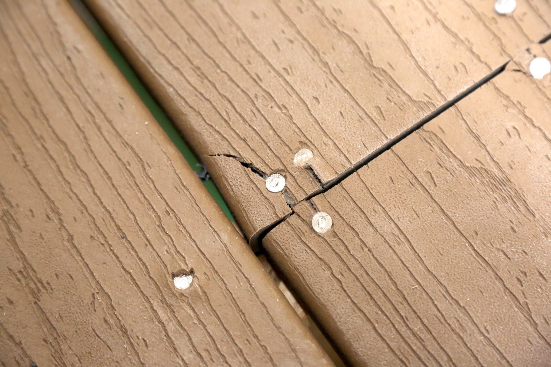
Damaged floor boards.
OBSERVATION #28
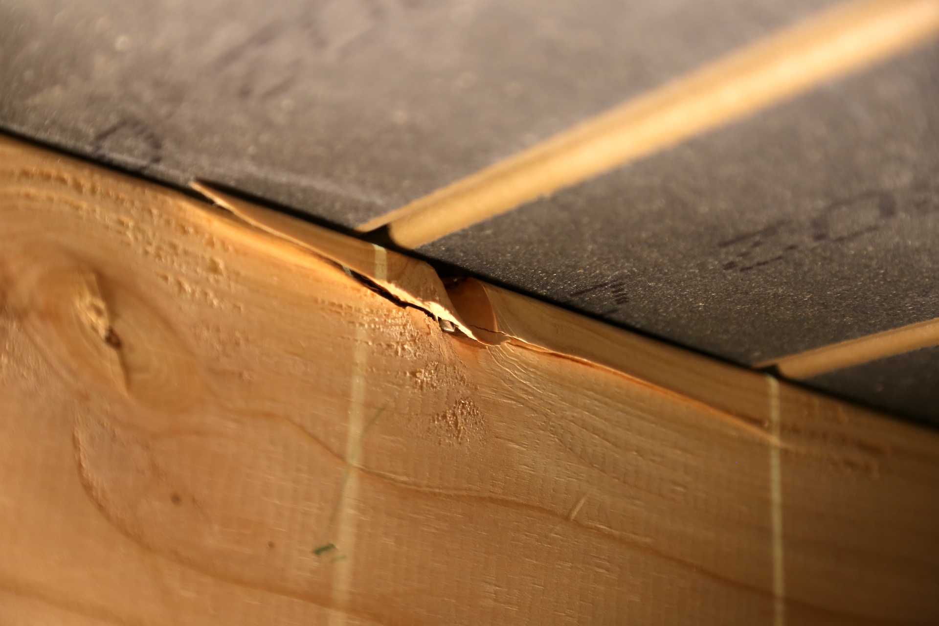
Some damage to the joist underneath the deck boards.
OBSERVATION #29
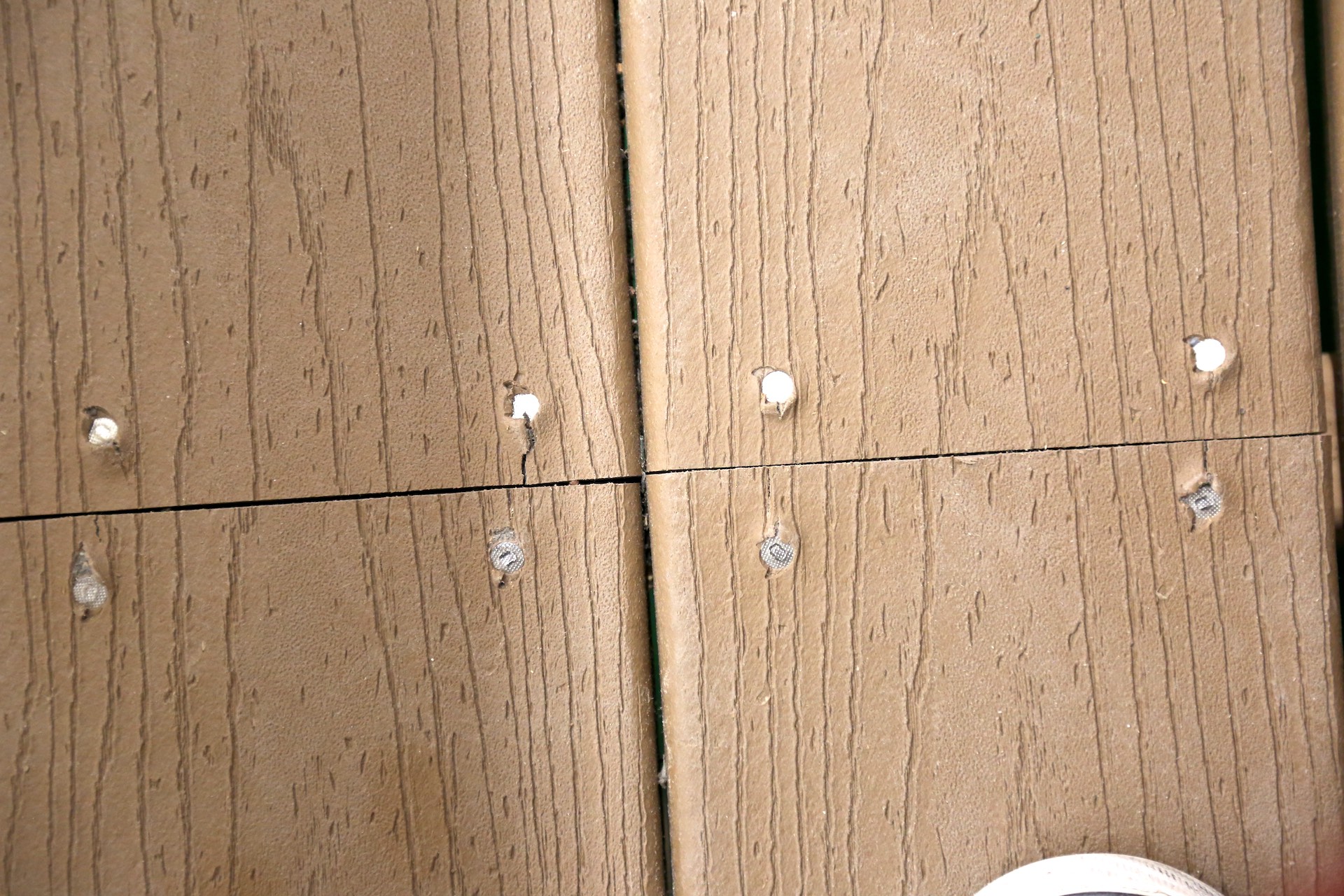
There are deck boards that are not staggered properly. Decking should be staggered so that butt joints don't land on the same joist side by side.
OBSERVATION #30
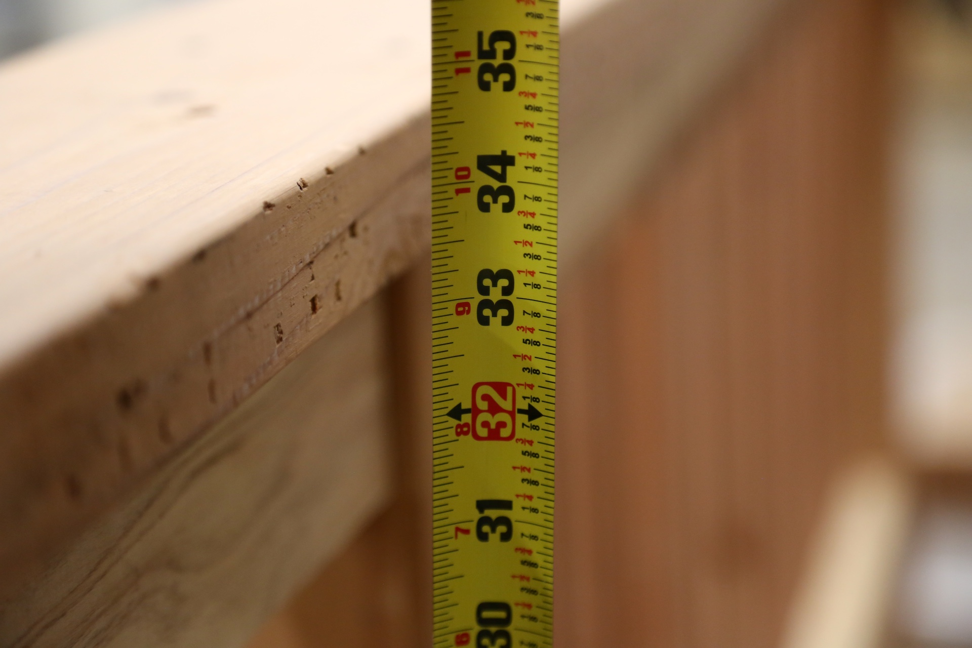
Most residential codes require the top of the guardrail to be at least 36 inches from the deck surface. Most commercial code height is 42 inches.
OBSERVATION #31
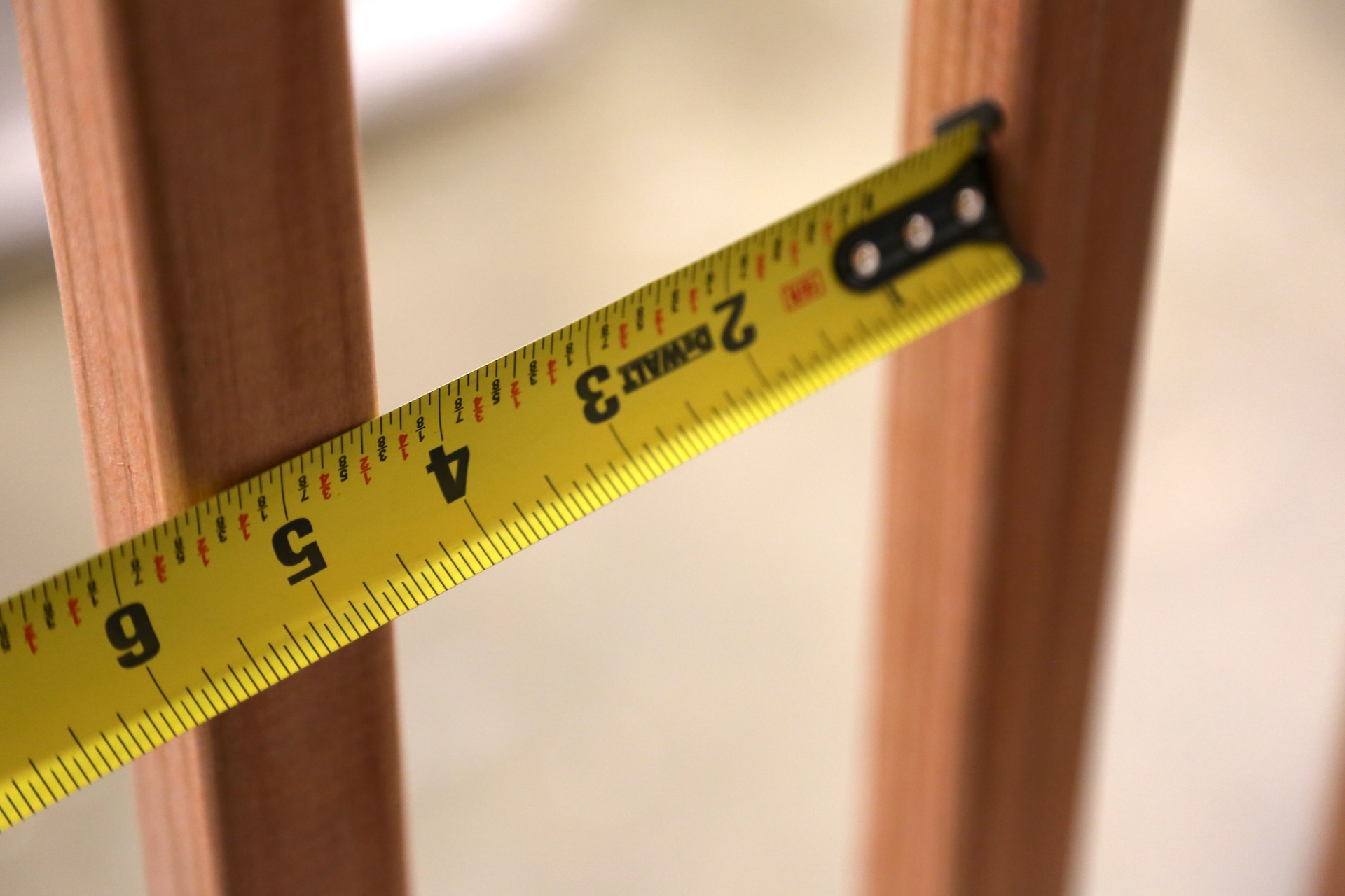
There is excessive open space between the guard in-fill components.
The guard in-fill components should not permit a 4-inch sphere to pass through them.
OBSERVATION #32

The guard in-fill components (or balusters) should be located on the interior side of the horizontal rails. As the deck ages, the fasteners will lose significant resistance to withdrawal.
OBSERVATION #33
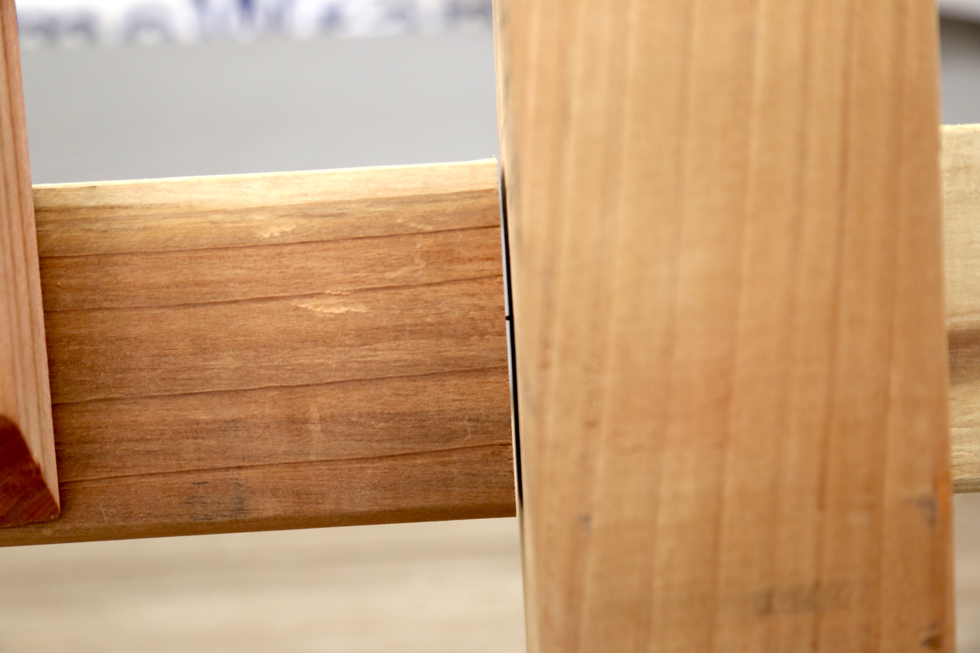
The guard in-fill components are attached to the posts with finish nails.
OBSERVATION #34

Drywall screws are used for fastening the guard components.
OBSERVATION #35
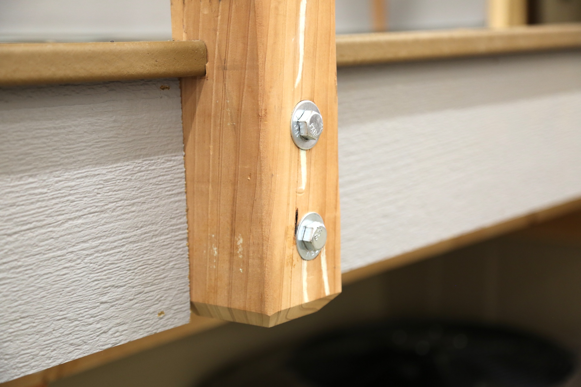
The guardrail posts are attached to the deck rim joist only. There are more reliable methods to attached the post, including metal connections.
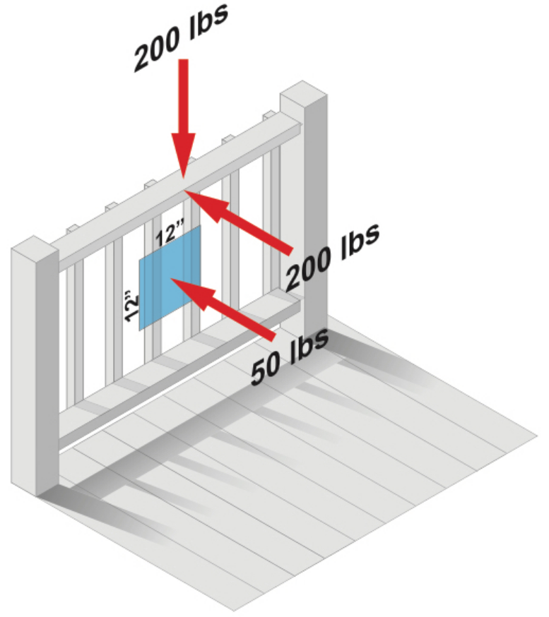
This common notched-type of attachment to the rim joist is permitted by many codes, but could become unsafe, especially as the deck ages. Because of leverage, a 200-pound force pushing the deck's guardrail outward causes a 1,700-pound force at the upper bolt attaching the post. It is difficult to attach deck guardrail posts in a manner that is strong enough without using deck guardrail post brackets.
Guard in-fill components, balusters and panel fillers must be able to withstand a horizontally applied load of 50 pounds on an area equal to one square foot.
There is one attachment at the bottom of a guardrail post that is not tight, where the washer is loose.
OBSERVATION #36
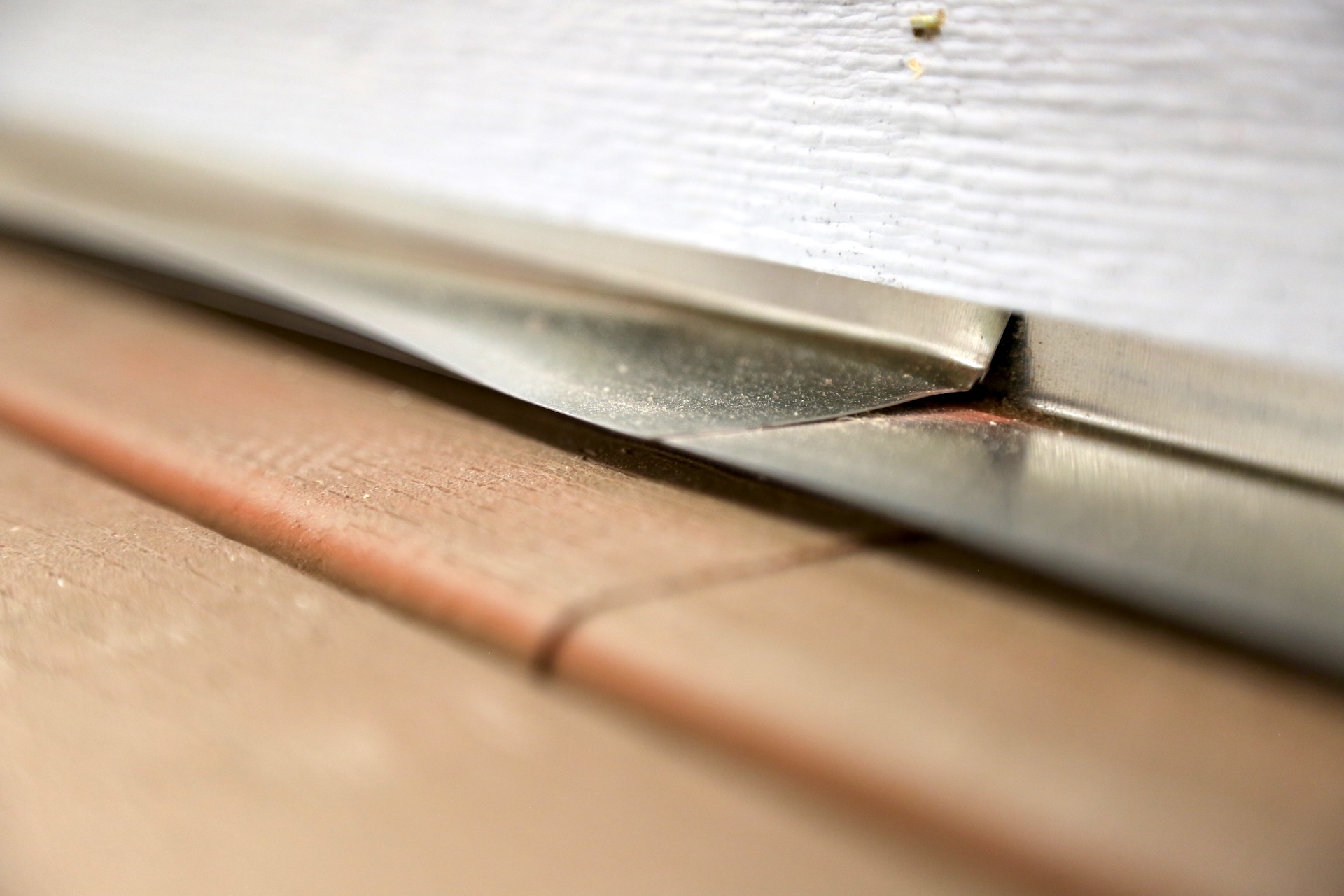
Inadequate clearance of the siding from the deck surface.
OBSERVATION #37
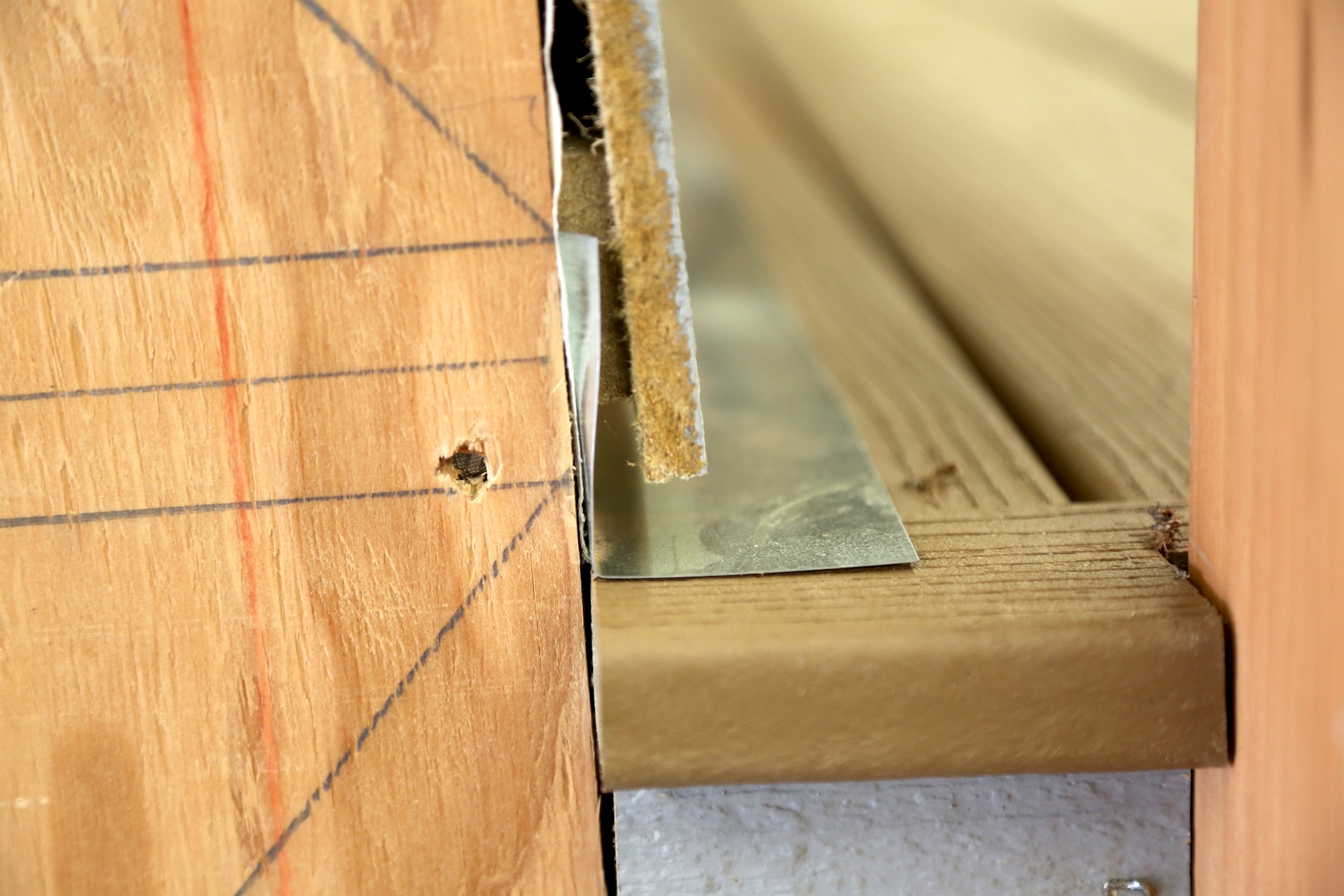
The Tyvek material should overlap the flashing at the ledger board area.
OBSERVATION #38
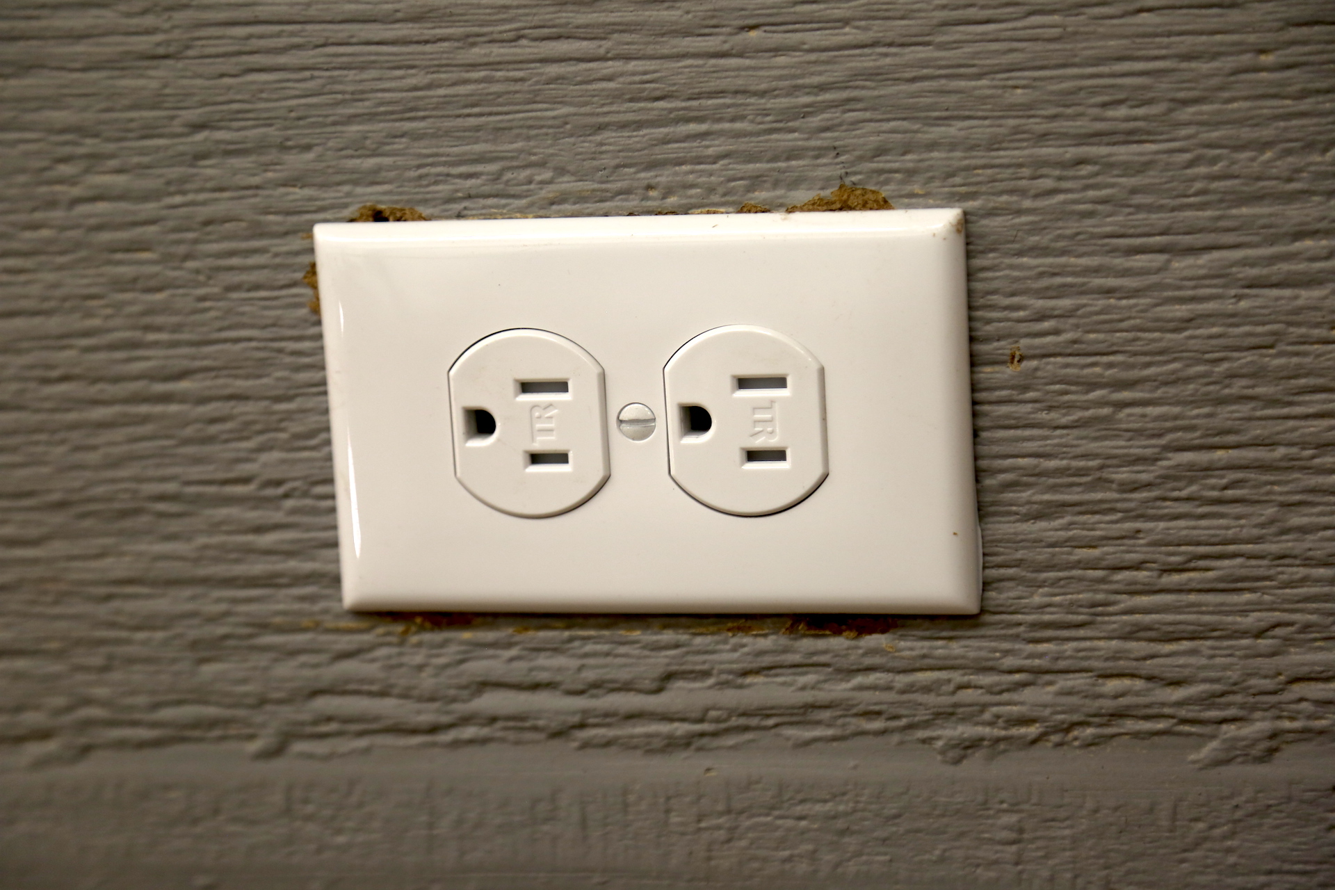
All deck receptacles should be GFCI-protected and weather-proof.
